
D7212 Operation & Installation Manual
Page 14
74-06913-000-B 2/96
© 1993-1996 Radionics
Premises Wiring
Run the necessary wiring throughout the premises and pull the wires into the enclosure.
EMI (Electro Magnetic Interference) may cause problems: EMI may occur if you install
the D7212 system or run system wires near the following:
• Computer network system
• Electrical lines, fluorescent fixtures or telephone cabling
• Ham radio transmitter site
• Heavy machinery and motors
• High voltage electrical equipment or transformers
• PBX telephone system
• Public service (police, fire departments, etc.) using radio communications
• Radio station transmitter site, or other broadcast station equipment
• Welding shop
If you think that EMI may be a problem, use shielded cable. The drain wire for the shielded
cable must have continuity from terminal 10 on the D7212 to the end of the wire run. If
continuity is not maintained, the shielded cable may aggravate potential noise problems
rather than eliminate them.
Connecting the drain wire to ground at other than terminal 10 may also produce problems.
If you cut the drain wire to install devices be certain to splice it together. Solder and tape
all splices.
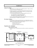
Installing the D7212 Assembly
1.
Place the D7212 assembly over the inside back of the enclosure, aligning the large
rectangular openings of the mounting skirt with the mounting hooks of the enclosure.
Slide the D7212 down so it hangs on the hooks. See Figure 2.
2.
Remove the tape from the #6x1/4" screw in the mounting tab on the D7212 assembly.
The screw passes through the mounting tab and into the skirt mounting hole in the
enclosure. Tighten the screw to secure the D7212 assembly in the enclosure.
3.
Connect earth ground to the panel before making any other connections. See
Connecting Earth Ground below.
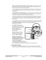
Connecting Earth Ground
Terminal
10
To help prevent damage from electrostatic charges or other transient electrical surges,
connect the D7212 to earth ground at terminal 10 before making any other connections. A
grounding rod or cold water pipe are recommended earth ground references.
Do not use telephone or electrical ground for the earth ground connection. Use 16
AWG wire when making the connection. Do not connect any other panel terminals to earth
ground.
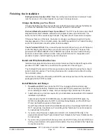
Locking the Reset Pin
Locking the Reset Pin disables the panel. See Figure 3. The D7212 ignores the command
centers and points while disabled. CALL FOR SERVICE appears in command center
displays while the pin is locked down.


