background image

D7212 Operation & Installation Manual

Page  16

74-06913-000-B 2/96

© 1993-1996 Radionics

Finishing the Installation

Earth ground and reset pin first: Make the earth ground connection to terminal 10 and
lock the reset pin in the closed position if you haven’t already done so.

Charge the Battery as You Finish

Connect the battery and then the transformer so that the panel can charge the battery as
you finish the installation. See the 

Power Supply  section for instructions.

On-board Buzzer Sounds at Power Up and Reset:  The D7212 performs a series of self
diagnostic tests of its hardware, software, and program at power up and at reset. The
buzzer on the D7212 sounds during the tests. They take about 10 seconds to complete.

If the panel fails any of the tests, the buzzer continues sounding and a system trouble
message appears at the command centers. See 

Self Diagnostics in the Trouble Shooting

section for a description of each system trouble message.

Touch Terminal 10 first: If the on-board buzzer sounds briefly when you touch the panel,
you're discharging any static charge you may be carrying to the panel. The panel may
generate WATCHDOG RESET and/or PARAM FAIL events. See the 

Trouble Shooting

section for a description of these events.  Always touch terminal 10, the panel's earth
ground connection,  before beginning work on the panel.

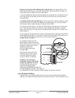
Install and Wire Detection Devices

Install and wire detection devices and command centers at their locations throughout the
premises. DO NOT make the connections at the panel end of the wiring yet.

The 

On-Board Points section of this manual contains instructions for wiring the on-board

points to detection devices. The 

Arming Devices section contains instructions for wiring

the command centers.

Instructions for wiring the off-board point POPIT sensor loops are found in the instructions
packaged with the POPIT modules.

Install Modules and Relays

1.

Power Down First: Power down the D7212 by unplugging the transformer and
disconnecting the battery. Radionics recommends that you power down the D7212
when installing modules or relays, or when making wiring connections to the panel.

2.

Install and wire any modules required for your installation as described in the module’s
installation instructions.

Instructions for the D8125 POPEX Module, the D8128A OctoPOPIT Module, the
D8129 OctoRelay Module, the D811 Arm Status Relay Module, and the D128 Dual
Phone Line Switcher appear in this manual.

See 

Off-board Points for D8125 and D8128A instructions. See Relays for D8129 and

D811 instructions. See 

Dual Line Transmitting in the Telephone Connections section

for instructions for the D128.

3.

If you are using the power outputs at terminals 7 or 8, install a D136 relay in the
appropriate sockets. See 

Programmable Power Outputs in the Power Outputs section

for instructions.

4.

If you are using a ground start phone system, insert a D136 relay in socket K6/J5 and
set the ground start pin in the ground start position. See 

Ground Start in the Telephone

Connections section.

Summary of Contents for D7212

Page 1: ...D7212 Control Communicator Operation and Installation Manual 74 06913 000 B 2 96 1993 1996 Radionics ...

Page 2: ...io communications Operation of this equipment in a residential area is likely to cause harmful interference in which case the user will be required to correct the interference at his own expense Part 68 This equipment complies with Part 68 of FCC rules A label contains among other information the FCC registration number and ringer equivalence number REN If requested this information must be provid...

Page 3: ...nics Customer Service for repair and or warranty information If the trouble is causing harm to the telephone network the telephone company may request that you remove the equipment from the network until the problem is resolved User repairs must not be made and doing so will void the user s warranty This equipment cannot be used on public coin service provided by the telephone company Connection t...

Page 4: ... Data Expansion Loop 37 Wiring Data Expansion Loops to POPEX Modules 38 POPIT Sensor Loops 38 Point Assignments 39 Introduction 7 Areas and Accounts 8 Communicator 8 D1255 Alpha III Command Center 8 Keyswitch 8 Event Memory 9 Event Log 9 EMI Lightning Transient Protection 9 Programming 9 Other Features 10 D7212 Control Communicator Assembly 11 Ordered Separately 11 Listings and Approvals 12 Fire 1...

Page 5: ...2 54 D7212 Faceplate 55 Quick Reference Terminal Description 56 Installation Guide for UL and Fire Applications57 Listings and Approvals 57 Fire 57 Burglary 57 Optional Compatible Equipment 58 Burglary Applications 58 Fire Applications 58 System Chart 60 System Wiring Diagram Issue A 61 Current Rating Chart for Standby Battery Calculations 62 Standby Battery Requirements 63 Standby Battery Calcula...

Page 6: ... Line Switcher 31 Figure 11 On board Point Sensor Loop Wiring 32 Figure 12 D8125 Connections 36 Figure 13 Typical Expansion Loop POPIT Configuration 38 Figure 14 D7212 Program Record Sheet 39 Figure 15 POPIT Labels 40 Figure 16 D8128A OctoPOPITs 42 Figure 17 D8129 OctoRelay Connections 48 Figure 18 Power at Command Centers 51 Figure 19 Keyswitch Wiring 52 Figure 20 Reset Pin 53 Figure 21 Programme...

Page 7: ...Input Transponder points Each off board point requires a POPIT module D8127 POPIT modules require the D8125 POPEX module The D8128A OctoPOPIT module combines eight POPITs in a single module and does not require the D8125 POPEX module D7212 D8128A OctoPOPIT combines 8 POPIT Points in one module D8125 Interface for D8127 POPITS Points 9 48 D8129 OctoRelay provides alarm and auxiliary relay output Ot...

Page 8: ...rogram the panel to direct reports to four separate phone numbers Adding the D128 Dual Phone Line Switcher module allows you to connect and supervise a second phone line D1255 Alpha III Command Center The D1255 Alpha III Command Center offers complete system control and annunciation The D1255 features an illuminated keypad a 16 character English language display and a built in speaker that offers ...

Page 9: ...d an event modifier showing the previous arming state All events and their modifiers are stored even if the D7212 does not send a report for them You can view the log at a D1255 Command Center print it locally using the D9131 Parallel Printer Interface and a parallel printer or upload it to a D5300 Remote Account Manager II RAM II See S View Log in the Security System User s Guide 71 06141 000 for...

Page 10: ... Supervision of AC primary power battery secondary power ZONEX and SDI buses CPU Central Processing Unit 1 printer and telephone lines Automatic system test reports Remote access for programming diagnostics and log uploads using the Radionics D5300 Remote Account Manager II RAM II RAM Line Monitor answering machine work around Fire Alarm Verification Programmable Alarm Output Programmable Relay Ou...

Page 11: ...mpatibility Technogram 73 06143 000 UL 1023 Household Burglary Technogram 73 06806 000 Point Chart Label 79 06916 000 Eight 1k ý end of line resistors Two 14 18 AWG color coded battery leads Security System Owner s Manual 71 06633 000 D7212 Assembly D7212 PC board Faceplate shield Mounting Skirt One 6x1 4 screw Ordered Separately Order the following to complete a basic 8 point D7212 installation D...

Page 12: ... the California State Fire Marshal NYC MEA Approved by New York City s Materials and Equipment Acceptance System Factory Mutual FM Submitted for evaluation by Factory Mutual Burglary UL Underwriters Laboratories lists the D7212 Control Communicator for Central Station Local Police Connect Mercantile Safe and Vault and Grade A Household systems Department of Defense DOD The D7212 has been granted a...

Page 13: ...144 000 Before you begin the installation of the D7212 you should be familiar with the operation of the D5200 programmer or the RAM II remote programmer Enclosure Options Mount the D7212 Control Communicator assembly in any of the Radionics enclosures listed below Refer to the Installation Guide for UL and Fire Applications in this manual to determine if your application requires a specific enclos...

Page 14: ...splice it together Solder and tape all splices Installing the D7212 Assembly 1 Place the D7212 assembly over the inside back of the enclosure aligning the large rectangular openings of the mounting skirt with the mounting hooks of the enclosure Slide the D7212 down so it hangs on the hooks See Figure 2 2 Remove the tape from the 6x1 4 screw in the mounting tab on the D7212 assembly The screw passe...

Page 15: ...D5300 RAM II programmers If you place the reset pin in the disable position with one or more areas disarmed there must be an entry in the Answer Disarmed program item to use RAM II If you place the reset pin in the disable position when all areas are armed there must be an entry in the Answer Armedprogram item See RAM Parametersin the D7212 Program Entry Guide 74 06915 000 Releasing the reset pin ...

Page 16: ...on devices and command centers at their locations throughout the premises DO NOT make the connections at the panel end of the wiring yet The On Board Points section of this manual contains instructions for wiring the on board points to detection devices The Arming Devices section contains instructions for wiring the command centers Instructions for wiring the off board point POPIT sensor loops are...

Page 17: ...s to the panel Combined continuous current draw for terminals 3 8 and 32 and the Accessory Connector J2 cannot exceed 1 4A See the Power Outputs section for help Programming the Panel If you haven t created a program for the panel review the D7212 Program Entry Guide 74 06915 000 Check to be certain you have all the required accessory modules installed for the features you want to use Use the D520...

Page 18: ... default sets AC Fail Time at 10 seconds Installing the Transformer Do not short the terminals of the transformer Shorting the terminals opens the internal fuse causing permanent failure Connect the transformer to terminals 1 and 2 of the panel before plugging it into the power source Use 18 AWG minimum wire to connect the transformer to the panel Wire length should be kept as short as possible Ma...

Page 19: ...se caution when working with the positive lead and terminal 5 Always disconnect the positive red lead from the battery before removing it from terminal 5 Replacement Radionics recommends battery replacement every 3 to 5 years under normal use Exceeding the maximum output ratings or installing the transformer in an outlet that is routinely switched off causes heavy discharges Routine heavy discharg...

Page 20: ...from being damaged by deep discharge When AC power restores the load shed relay resets and battery voltage is again available Reset or power down required for shorted battery If the D7212 determines the battery is shorted it uses the load shed relay to disconnect the battery You must reset or power down the panel after correcting the problem to reset the load shed relay and reconnect the battery R...

Reviews: