D9412G/D7412G Operation & Installation Guide
43488D
Page 26
© 2002 Radionics
D9412G/D7412G
battery lead to Terminal 5, and then to the positive (+) side of the battery.
High Current Arcs Possible
The positive (red) battery lead and Terminal 5 can create high current arcs if shorted to other terminals or the
enclosure. Use caution when working with the positive lead and Terminal 5. Always disconnect the positive
(red) lead from the battery before removing it from Terminal 5.
CAUTION
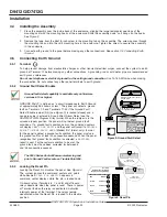
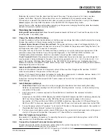
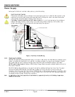
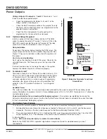
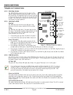
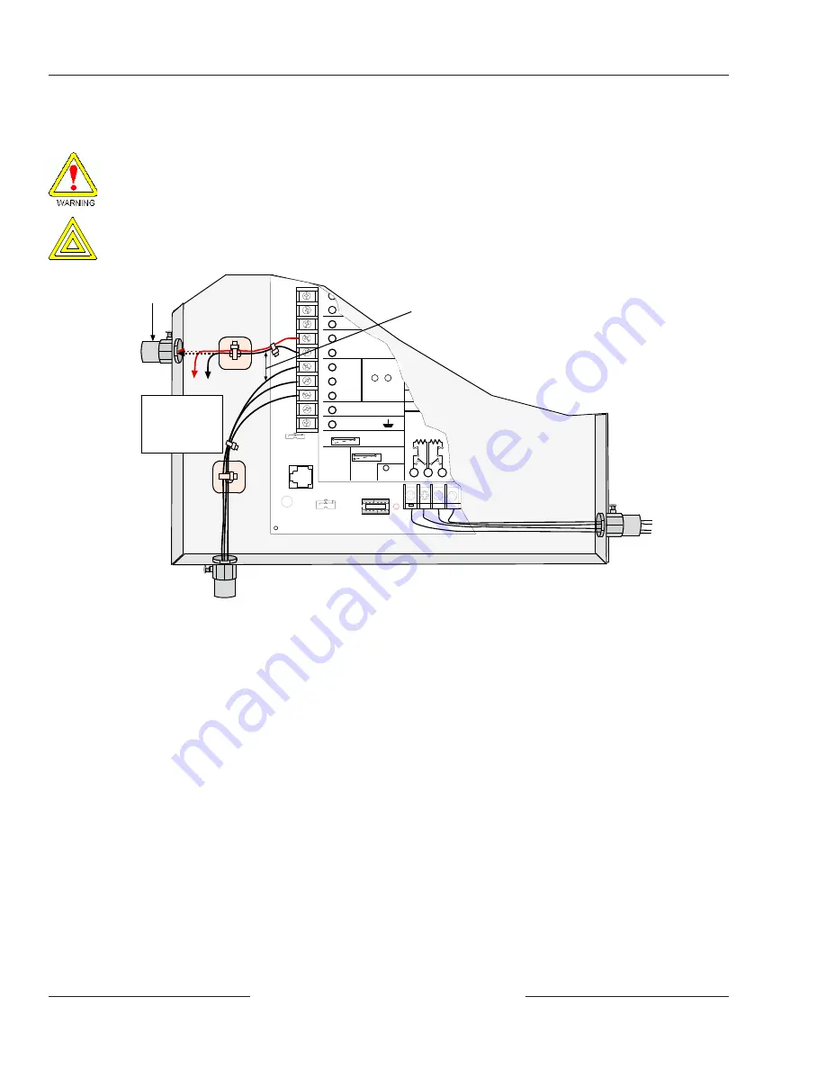
The Battery Terminals and Wires are NOT Power Limited. A ¼ in. (6.4 mm) spacing must be maintained
between the battery terminals, battery wiring and all other wiring. Battery wiring may not share the same
conduit, conduit fittings or conduit knock-outs with other wiring. See Figure 5.
¼ in. (6.4 mm) minimum
Option
Wires
Output or
Zone Wires
Only required if
external batteries
are used
EARTH GROUND
COMMON
BATTERY NEGATI
Maximum Charging
Current 1.4 Amps.
BATTERY POSITIVE ONLY
RELAY A
RELAY B
RELAY C
+ AUX
1
2
3
4
5
6
7
8
9
10
D
PROGRAMMABLE
ALARM OUTPUTS
Terminals
Requires Optional
D136 Relay
In ALT ALARM
& SW AUX
&
7
8
GROUND FAULT DETECT
Enabled
Disabled
PHONE
LED
R E D
ON WHEN
COMMUNICATING
OFF WHEN IDLE
LOOP START
GND START
GROUND START
12
11
13
Point 1 Point 2
GROUND START
Requires
Relay # D136 in
Ground
Start Socket
Battery Wires
To Batteries
To ensure proper
spacing secure
wires using
Tie-Wraps or
similar devices.
Figure 5: Non Power Limited Wiring
4.2.3
Replacing the Battery
Radionics recommends battery replacement every 3 to 5 years under normal use. Exceeding the maximum output
ratings, or installing the transformer in an outlet that is routinely switched off, causes heavy discharges. Routine
heavy discharges can lead to premature battery failure. Record the date of installation directly on the battery.
D8132 boosts battery backup: Adding a D8132 Battery Charger Module supports additional batteries of up to 36
Ah capacity if required.
The D8132 Battery Charger Module can be used to connect two additional batteries for a total of four. The panel
plus any connected D8132 Modules and AUX power supplies must be on the same AC circuit so they will
discharge evenly if AC power fails. The number of D8132 Modules is determined by the number of available outlets
on the same circuit. See
Standby Battery and Current Rating Chart in the D9412G/D7412G Approved Applications
Compliance Guide for battery standby time calculations.
Note:
In applications where the supervision of two batteries is required by the AHJ, a D113 Battery Supervision
Module must be used.
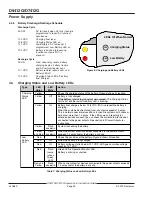
Power Supply


