
D9412G/D7412G Operation & Installation Guide
43488D
Page 58
© 2002 Radionics
D9412G/D7412G
SDI Devices
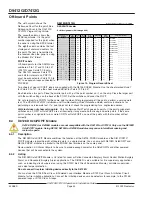
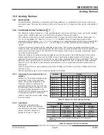
11.4
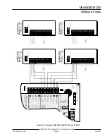
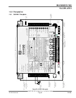
D9210B Wiegand
TM
Control Interface Module
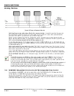
The Radionics D9210B Wiegand
TM
Control Interface
Module is a 4-wire powered device providing
connections for an access door point and door strike.
The D9412G can supervise eight Wiegand
TM
Control
Modules, and the D7412G can supervise two. Each
D9210B supports one door to control access.
Programming allows each access door to be
configured independently.
Using Wiegand
TM
style cards or tokens, the D9210B can
allow access for up to 996 cards/tokens on the
D9412G, 396 on the D7412G. User access authority
can be configured to restrict access to certain doors or
to certain periods of time. The reading of access cards,
in addition to granting access, can control whether the
system will disarm. Used with the D9412G, the D9210B
recognizes 249 master users by user name, passcode,
and access authority. The D9210B recognizes 99
master users when used with the D7412G. Each
master user will support three sub-users with unique
cards/tokens having the same access level as the
master user.
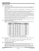
11.4.1
Switch Settings
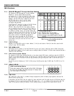
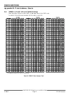
Switches on the D9210B assign a unique address (1 to 8) to each module.
Table 16 shows the correct switch
setting for each D9210B address.
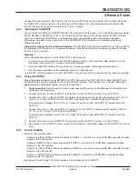
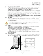
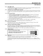
11.5
SDI Address 80
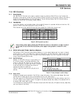
SDI Address 80 is available on the D9412G/D7412G panels and allows bi-directional SDI to RS232 information.
The intent of this address is for use with home or building automation software. A D9133 Serial Interface Module is
required for this application.
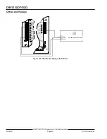
11.5.1
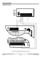
D9133 Serial Interface Module
The Radionics D9133 Serial Interface Module is a four-wire powered SDI device providing connection for RS232
devices to the D9412G/D7412G panels. The D9133 uses a specific communication protocol that is provided upon
request. Please contact Radionics Technical Support Monday through Friday from 5 AM to 5 PM Pacific Time at
800-538-5807.
The D9133 can be installed up to 1,000 ft. (305 m) away from the panel using 18 AWG wire. The D9133 is not UL
Listed.
11.5.2
Address Settings
11.5.3
Supervision
The supervision of the D9133 is available through programming which includes proper operation between the
D9133 and the control panel.
If supervised and the D9133 does not respond to panel supervision polls, the panel sends an SDI failure report to
the receiver if it fails to communicate with the D9133 and
SERVC SDI 80
displays at the command center. The
report to the receiver includes the address of the troubled module to indicate which module needs service.
Door
Module
1
2
3
4
5
6
1
ON
ON
ON
*
ON
ON
2
OFF
ON
ON
*
ON
ON
D7412G maximum
3
ON
OFF
ON
*
ON
ON
4
OFF
OFF
ON
*
ON
ON
5
ON
ON
OFF
*
ON
ON
6
OFF
ON
OFF
*
ON
ON
7
ON
OFF
OFF
*
ON
ON
8
OFF
OFF
OFF
*
ON
ON
* Fail Safe Mode (Switch 4)
ON = If SDI Bus Fails, relay energizes.
OFF = If SDI Bus Fails, relay de-energizes.
NOTE: Switches 5 and 6 MUST remain in the ON
position.
Table 16: Access Control Module Address
Switch Settings
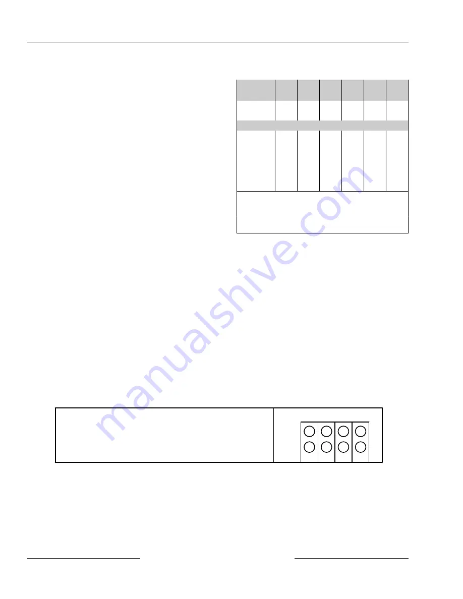
D9133 Serial Interface Module
There are no jumper settings required for the D9133 (SDI Address
80) for home or building automation purposes. All Jumper shunts
must be removed for this setting.
1
2
3
4
80