1997 Radionics All rights reserved
The Radionics logo is a registered trademark of Radionics,
1800 Abbott Street, Salinas, CA 93901, USA
74-07649-000-B 01/97
D9024/D10024 Installation
Page 12 of 17
C.3.d. D9051 Module Connection to the Control Module
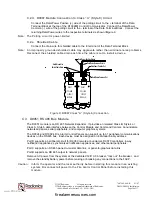
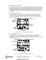
The 10-wire ribbon connector from the D9067 Polling Circuit Module plugs into the 10-pin socket
immediately below it. The D9051 8-wire ribbon connector plugs into the lower socket.
See
Figures 10 and 11.
Caution: Do not try to plug the 8-wire ribbon connector into the upper (10-pin) socket.
C.3.e. Connecting Circuit Wiring to the D9051
Circuit Length is the distance over the circuit wire from the connection at the D9051 Module to
the most distant device and back to the D9051 Module. The maximum RS 485 circuit length is
4,920 ft. using shielded twisted pair wiring such as the Data Grade Cable D293, or non-shielded
18 gauge cable from Atlas, Guardian Sound & Security, or their equals.
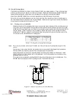
RS 485 Bus Circuit Length
Wire Gauge
Up to 4,920 ft.
18
Table 4: RS 485 Peripheral Circuit Length/wire Gauge
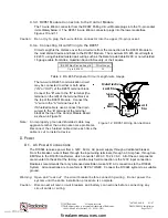
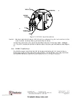
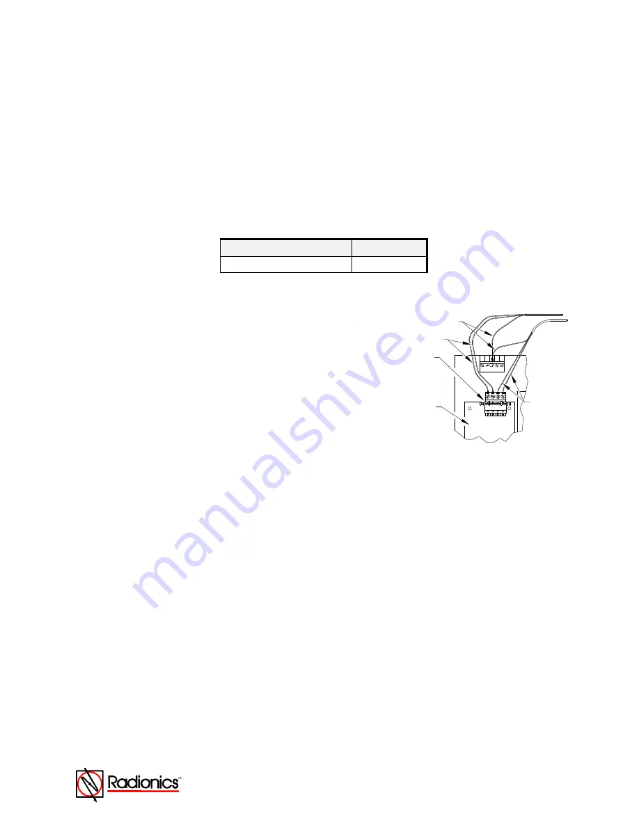
The two-wire RS 485 communication circuit
may be connected to either or both sides
(“IN” or “OUT”) of the D9051 terminal block.
Connect the “B” wire to the “B” terminal (the
terminal on the left) of the terminal block at
the top of the D9051 Module. Connect the
“A” wire to the “A” terminal next to it.
If Shielded cable is used, connect the drain
wire(s) to the “E” terminal of the terminal
block at the top of the Control Module Board
as shown in
Figure 12
.
Note: An improperly grounded shielded cable may
aggravate rather than eliminate noise problems.
Reconnect the shielded cable drain each time the
cable is cut to install a device.
D. Power
D.1. AC Power Connections
The D10024 receives power from a 120
V,
60 Hz, AC power supply through a dedicated breaker.
From the breaker, current flows through the input wiring terminals, through a 3 Amp fuse, through an
EMI filter to the D1605 transformer, which converts 120
V
AC To 24
V
AC. All of these components
are mounted to the skirt at the factory, and the only field connection is the 120V input connection.
Radionics recommends that only a licensed electrician make 120
V
AC connections to the D10024
System. All connections are to conform to NFPA 70/NEC. Connect the D10024 system to a suitable
ground.
Warning: Open and “lock out” the circuit breaker before connecting wiring. Do not power the
system until the entire installation procedure is complete.
Caution: Disconnect all main circuit breakers and battery connections before connecting any
circuit cards or wiring.
+
+
- LOOP
RS 485
D9051
D9051
Module
Terminal
Block
5
-
Shielded Cable Drain
A and B
Wires
A and B Wires
Figure 12: D9051 Wiring Connections
www.PDF-Zoo.com
firealarmresources.com


