1997 Radionics All rights reserved
The Radionics logo is a registered trademark of Radionics,
1800 Abbott Street, Salinas, CA 93901, USA
74-07649-000-B 01/97
D9024/D10024 Installation
Page 7 of 17
C. Control Panel Components
Caution: Disconnect all main circuit breakers and battery connections before c
onnecting any
circuit cards.
C.1. Control Module
Conventional reporting devices initiate alarm conditions through the Fire Alarm Control Panel
(FACP). The analog FACP interacts with its reporting devices in a system that is constantly
measuring not only its environment, but also its own ability to report on that environment. The FACP
analyzes the measurements, compares them with other measurements, thresholds, the reported
contamination of the devices, the time of day, and other programmed standards. Depending on the
results of these comparisons, the Analog FACP may initiate an alarm, service, or a trouble condition.
The FACP supervises and responds individually to each analog device in the circuit.
When the analog system configures the polling circuits, the control panel down-loads a number of
parameters, which have been programmed into the panel and are stored in the Central Processing
Unit (CPU), to each analog device. These levels can be altered through the front panel or PC
programming. Each device is programmed for:
•
Alarm Level, High Sensitivity
•
Alarm Level, Low Sensitivity
•
Service Level
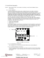
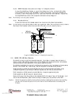
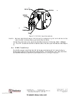
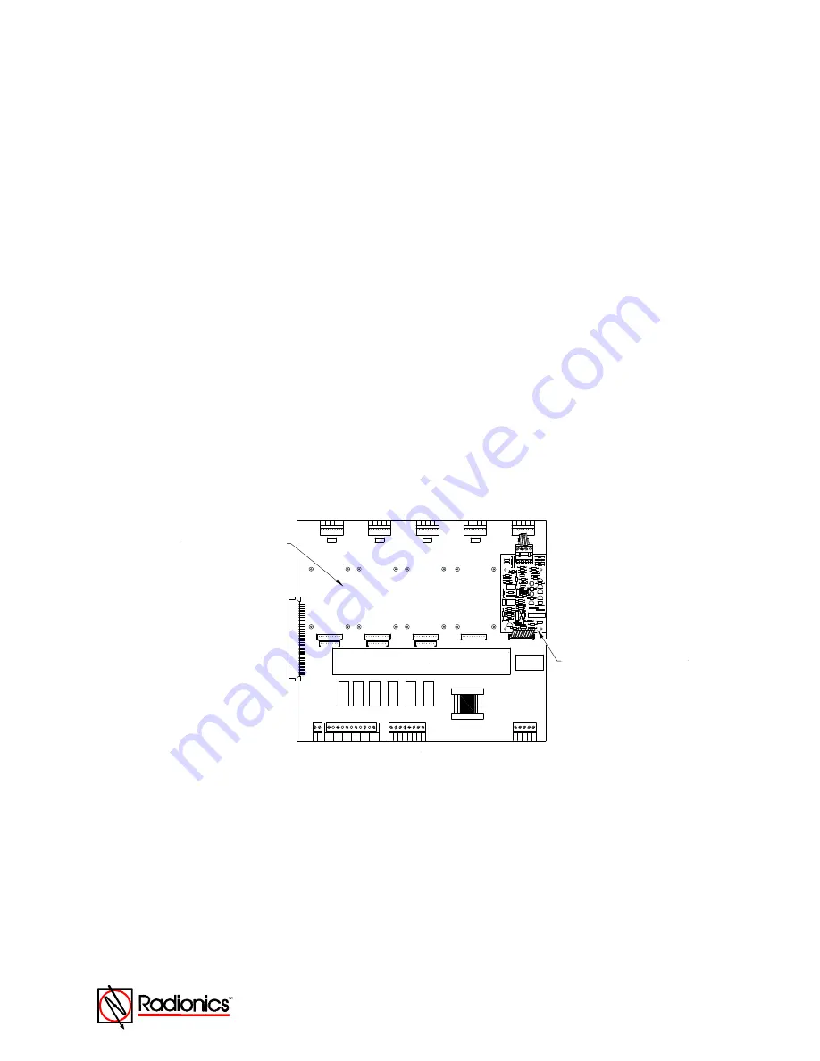
The D10024M or D9024M Control Module is the Input/output Printed Circuit Board, beneath which is
the Central Processing Unit (CPU), and the Backplane Board. The Control Module, the On Board
Power Supply, the Transformer, and the input wiring connections are all mounted on a skirt. The
hardware needed to mount the board in the enclosure is attached to the skirt.
+
SOUNDER
OUTPUTS
PL_LOOP3
N/O
RELAY 2
N/C
24V.AUX.
0V
.
+2
4V
.
AUX RELAYS
N/O
COM
N/C
RELAY 1
PORT-D
PL_LOOP5
COM
A-
A+
B-
B+
C-
C+
D-
D+
PORT-C
PL_LOOP4
PORT-B
E
+
-
+
- LOOP
5
LOOP
E
+
-
+
-
4
E
+
-
-D
C
1
2
EA
RT
H
+D
C
+
- LOOP
3
-
E
-
+
LOOP
2
+
-
E
-
+
LOOP
1
PL_LOOP2
D10024M Control Module
D9067 Polling Circuit Module
Figure 4: D10024M Control Module
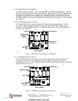
C.1.a. Control Module Installation
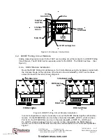
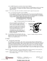
Use the attached nuts to mount the skirt to the D9109A Enclosure as shown in
Figure 5
.
C.1.b. Front Panel Display Connection
Attach the Enclosure door and connect the 16-pin ribbon connector from the front panel display
to the Control Module. Connect the Display Panel Ground Strap to the enclosure ground stud.
See
Figure 5
.
www.PDF-Zoo.com
firealarmresources.com


