5
Routing
88
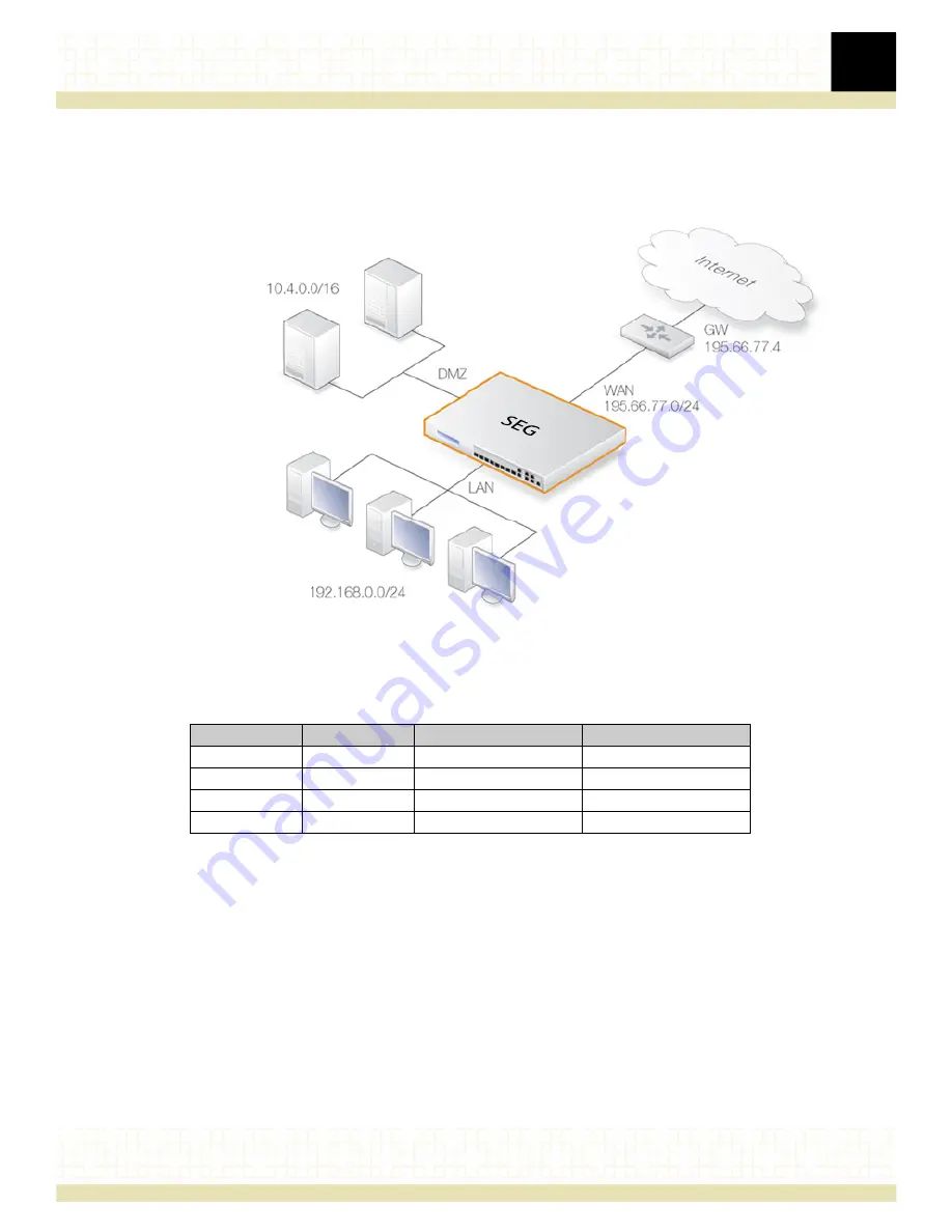
Typical routing scenario
The
diagram
below
illustrates
a
typical
SEG
usage
scenario.
Figure 5. A typical routing scenario
In
the
above
diagram,
the
LAN
interface
is
connected
to
the
network
192.168.0.0/24
and
the
DMZ
interface
is
connected
to
the
network
10.4.0.0/16
.
The
WAN
interface
is
connected
to
the
network
195.66.77.0/24
and
the
address
of
the
ISP
gateway
to
the
public
Internet
is
195.66.77.4
.
The
associated
routing
table
for
this
would
be
as
follows:
The
above
routing
table
provides
the
following
information:
•
Route
#1
All
packets
going
to
hosts
on
the
192.168.0.0/24
network
should
be
sent
out
on
the
sfp1
interface.
As
no
gateway
is
specified
for
the
route
entry,
the
host
is
assumed
to
be
located
on
the
network
segment
directly
reachable
from
the
sfp1
interface.
•
Route
#2
All
packets
going
to
hosts
on
the
10.4.0.0/16
network
are
to
be
sent
out
on
the
dmz
interface.
For
this
route
also,
no
gateway
is
specified
since
there
is
no
“hop”
via
another
router
to
the
destination
network.
Route
Interface
Destination
Gateway
1
sfp1
192.168.0.0/24
2
dmz 10.4.0.0/16
3
wan 195.66.77.0/24
4
wan all-nets-ip4 195.66.77.4


