RADIUS
Product
Description
PDR 121
iom_pdr121_04_r02.doc
Rev 02
Page 15 (67)
7 The PDR 121 Radio Transceiver Functionality
This chapter describes the PDR 121 radio functionality.
7.1 PDR 121 Operation Blocks
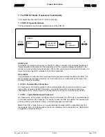
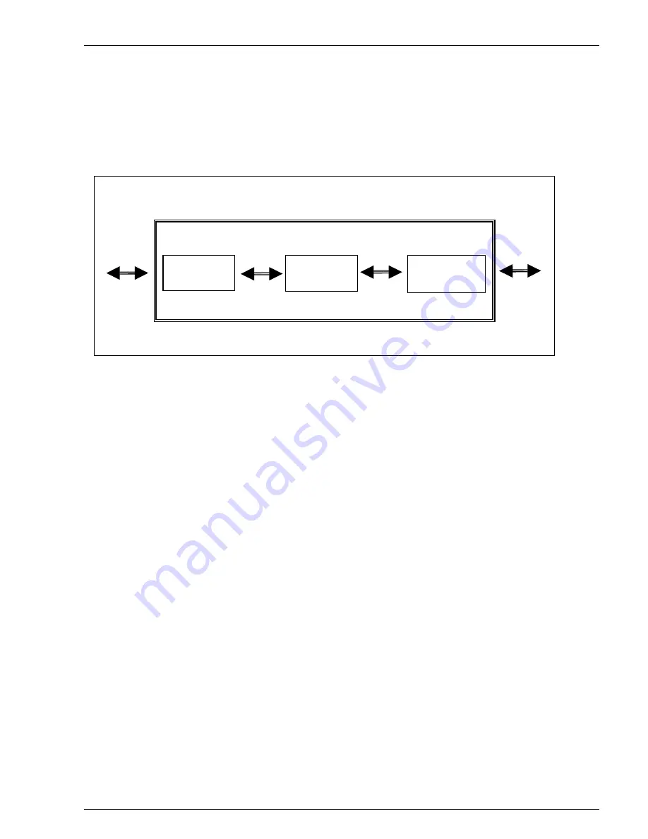
The figure below shows the basic building blocks of the PDR 121.
RS232 to RF
Serial data is received on the serial port. The MCU, (Micro Controller Unit), analyses the data and
frames the data and transfers it to the modulation unit. (The complete message is buffered in the
processor memory before being transmitted). The modem unit converts the received bit stream to a
4-level base-band signal for modulation of the radio transmitter.
RF to RS232
The modulation unit decodes the 4-level base-band signal and forwards the data to the MCU. The
MCU analyzes the message and prints it on to the serial port, (or re-transmits via the radio if the
message should be repeated).
7.2 FEC - Forward Error Correction
On transmission, FEC bits are added to the transmitted data before being converted to a 4-level
signal. When receiving, the FEC information - and an FEC algorithm - is used to correct any
transmission errors. A large proportion of transmission errors can be corrected using the FEC.
7.3 CRC – Cyclic Redundancy Checksum
On transmission, a CRC byte(s) is added at the end of the data. The CRC byte is calculated based
on the data contents of the message. The receiver checks the CRC byte against the received data
and can detect any transmission errors. Corrupted messages are discarded.
Note!
If the CRC is faulty, there is no non-acknowledge message (NACK) transmitted back from
the receiving radio. All re-transmissions have to be initiated by the connected device. Normally this
is trigged by a response timeout.
RS232
RF
Radio
Transciever
4 level FSK
Modulation
MCU
PDR121


