RADIUS
Product
Description
PDR 121
iom_pdr121_04_r02.doc
Rev 02
Page 20 (67)
8 Operating the PDR 121
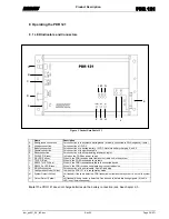
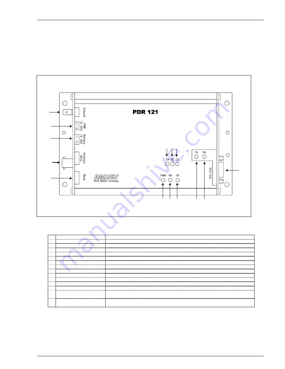
8.1 LED Indicators and Connectors
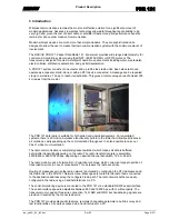
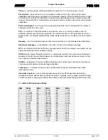
Figure 3. Packet Data Radio 121.
Name
Description
A
Earth/ground connection
For connection to the system’s earth/ground (Internally connected to PWR negative (-) pole.)
B
Voltage connection
For connection of 12VDC
C
Battery connection
For connection of a backup-battery, 12VDC. Note! No battery charging. See 9.3.
D
Coaxial connection
For connection of the antenna cable
E
Rbus connection
For connection of the Programming interface
ProgInt
F
PWR LED (Green)
Is lit when the PDR has power supply
G
RX LED (Yellow)
When lit, the PDR receives data from another radio unit in the system
H
TX LED (Red)
When lit, the PDR transmits data via radio
I
RS232 Tx LED (Red)
When lit, the PDR transmits serial data to connected device
J
RS232 Rx LED (Green)
When lit, the PDR receives serial data from connected device
K
RS-232 connection
For connection of the serial cable. 9-pole D-sub plug
L
Configuration Mode (Yellow)
Lit when the PDR 121 is in configuration mode
M System Detect (Yellow)
Lit (flashed) if the radio detects a PDR transmission from another system. I.e. not valid system
id.
N
Carrier Detect (Yellow)
Lit (flashed) when a carrier is detected. Can be used to detect interfering signals. (If the Rx
LED is not lit simultaneously).
Note!
The PDR 121 does not charge batteries via the battery connection jack. See chapter 9.3.
E
D
C
A
B
I
K
H
J
G
F
L M N

