RADIUS
Product
Description
PDR 121
iom_pdr121_04_r02.doc
Rev 02
Page 29 (67)
9.4 Serial Interface
The PDR 121 is connected to the control system / RTU via the RS-232 interface.
The serial data transmission is full duplex with selectable data speeds between 600 and 19200
bps, with or without parity. See chapter 12.6 for configuration.
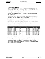
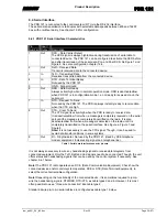
9.4.1 PDR 121 Serial Interface Characteristics
Pin
Number
Input /
Output
Description
1
Out
DCD – Data Carrier Detect
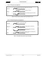
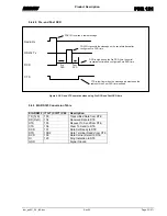
The DCD signal is always high/active during transmission of serial data to
connected device. The PDR 121 can be configured to activate the DCD before
and after transmission of the serial data. Pre- and Post DCD. Se Figure 7 and
Figure 8. See also configuration chapter 12.6.
2
Out
RxD – Received Data
Transmits received data to the connected device.
3
In
TxD – Transmitted Data
Receives transmitted data from the connected device.
4
In
DTR – Data Terminal Ready
Not used by the PDR 121.
5
-
GND – Signal Ground
6
Out
DSR – Data Set Ready
Always active/high when in normal operation mode. DSR is deactivated/low
when PDR 121 is in configuration mode. I.e. not ready to receive data on the
serial port.
7
In
RTS – Request To Send
Not used by the PDR 121. The PDR is always instantly ready to receive data
when the CTS are high.
8
Out
CTS – Clear To Send
The CTS signal is active/high when the PDR is ready to receive data.
It is deactivated/low from when a message is completely received on the serial
port until the message is completely transmitted on the radio. It is also
deactivated/low from when a message is detected on the radio until it is
completely transmitted on the serial interface. See Figure 6, Figure 7 and
Figure 8.
Note!
It is not necessary to use the CTS signal. Though, it can be used to
avoid data transfer collisions in some systems.
9
Out
RI – Ring Indicator. Not used by the PDR 121. (Used by DCE telephone
modem equipment. Indicates ring signal on a telephone line).
Table 1. Serial data interface connector pinouts.
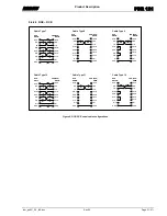
It is not always necessary to wire any handshaking signals to receive data telegrams from
connected equipment. Only the TxD, RxD and Gnd signals need to be connected. Though, the unit
offers status and handshaking signals that can be used by the control system if necessary. See
chapter 9.4.1 below.
Note!
The PDR 121 radio operates as a DCE, (Data Communication Equipment). Check how the
connected device and/or control system operates, DCE or DTE (Data Terminal Equipment), to
select the correct serial cable configuration.
Note!
Depending on the functionality of the connected device, it is sometimes required to jump-
wire the handshaking signals, DTR/DSR, RTS/CTS, as cable types 3 and 6. However, It is most
often possible to use a “three wire connection” like cable type 2.
Standard 9 wire pin-to pin serial cables are configured as cable type 1 below.

