RADIUS
Product
Description
PDR 121
iom_pdr121_04_r02.doc
Rev 02
Page 53 (67)
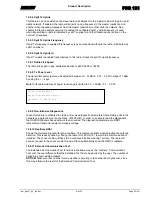
12.8.4 Split Tx Uplink
This feature can be enabled on the slave radio units adjacent to the master radio site to gain a split
uplink network. If enabled, the radio will transmit on one frequency to the master (uplink) and on
another when repeating messages from the master (downlink) to other units the network. See
chapter 8.9 for an example network. If enabled the configured split Tx uplink frequency is used
when transmitting to radio id indicated by split Tx uplink id, all other transmissions is done on the
normal Tx frequency.
12.8.5 Split Tx Uplink Frequency
If split Tx frequency is enabled this frequency is used when transmitting to the radio id indicated by
split Tx uplink id.
12.8.6 Split Tx Uplink Id
If split Tx uplink is enabled transmissions to this radio id uses the split Tx uplink frequency.
12.8.7 Radio Link Speed
The radio link speed in bps, available selection is 4800, 9600 or 19200.
12.8.8 Tx Power Level
The transmitter power level can be adjusted between 10…33 dBm / 0.01…2.0 W in steps of 1 dBm
by using the + / - keys.
Note!
VHF radio modules Tx power level range is limited to 20…33 dBm / 0.1…2.0 W.
12.8.9 Non-Intrusive Diagnostics
When this feature is activated the radio will receive diagnostic parameters from all radio units in the
network and write them out on the Rbus. (57600 N81). In order to be able to read the diagnostics
the RADIUS Windows based network tool is needed. The diagnostic parameters are RSSI,
temperature, transmitter power and supply voltage.
12.8.10 Realtime RSSI
Shows the Recieved Signal Strength in realtime. This feature is usable when adjusting the antenna
direction. This is easily done by chosing the radio ID of a PDR 121 to which the communication is
intended. The chosen radio will then start a continous bit stream during 1 minute. The radio will
send an request to the chosen radio ID and will then automatically show the RSSI in realtime.
12.8.11 Extended Communication Test
The Extended Communication Test functions in the same way as the ”ordinary” Communication
Test, with the soul difference that the Extended Test has to be aborted by the user. The number of
Failed
are shown within brackets.
NOTICE!
Make sure that no other communication is occuring in the network during the test, since
this may influence the result of the Extended Communication Test.
Select Tx Power Level
Adjust Tx Power Level with +/-
Selected : 33 dBm (2.00 W)


