October, 1996
6880902Z36-B
6-3
GM300 Radio Service Software Manual
Accessory Connector (16 Channel Models Only)
Customizing the Expanded Accessory Connector
6
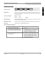
Active Level
RSS LOCATION
DEFINITION
The programmable pins are binary. They become active on either a high or low
voltage signal. Some non-standard accessories may not have the same active level
as the defaults.
DEFAULT/CHOICES
Default:
See Accessory Package default tables in Appendix H.
Choices:
■
High
■
Low
PROGRAMMING PROCEDURE
1. Press
F4
at the MAIN MENU to get to the
CHANGE/VIEW CODEPLUG MENU.
4. Press
Tab
or
Enter/Return
until the Active Level
field for the desired pin is highlighted.
2. At the
CHANGE/VIEW CODEPLUG MENU
,
press
F2
to get to the
RADIO-WIDE
screen.
5. Use the
↑ ↓
arrow keys to select the desired
choice.
3. Press
F9
to enter the ACCESSORY CONNEC-
TOR CONFIGURATION screen.
MAIN
MENU
➠
F4
➠
F2
CHANGE/
VIEW
➠
F9
RADIO
WIDE
➠
Tab
Active Level
field
ACCESSORY
SCREEN


