background image

https://harrissupplyind.com - To Order Parts Call 608-268-8080

NOTES 

980200  05/28/04 

5-6


Summary of Contents for RWB36

Page 1: ...h a r r i s s u p p l y i n d c o m T o O r d e r P a r t s C a l l 6 0 8 2 6 8 8 0 8 0 Operating Instructions ENG MODELS RWB36 WALK BEHIND SWEEPER Read instructions before operating the machine B 980200 03 11 08 ...

Page 2: ...___________ SERIAL NUMBER ______________________________ SALES REPRESENTATIVE _____________________ YOUR DEALER Name __________________________________________________________________________________________________ Address _______________________________________________________________________________________________ Phone Number ___________________________________________________________________...

Page 3: ...tery Recharge 4 1 Filter Maintenance 4 1 Cleaning Filter 4 1 Replacing Filter 4 1 Brush Maintenance 4 2 Replacing Adjusting Side Brush 4 2 Replacing Adjusting Main Brush 4 2 Belt Maintenance 4 2 Replace Main Brush Belt 4 2 Replace Side Brush Belt 4 3 Replace Drive Belt 4 3 Flap Maintenance 4 3 Replace Outer Side Flap 4 3 Replace Inner Side Flap 4 3 Replace Center Flap 4 3 Cable Maintenance 4 4 Rep...

Page 4: ... machine and its components in good working condition They are listed in this general order Batteries Brushes Belts Service Schedule Machine Troubleshooting MODEL _____________________________________ DATE OF PURCHASE ________________________ SERIAL NUMBER ____________________________ SALES REPRESENTATIVE ___________________ The PARTS LIST section contains assembled parts illustrations and corresp...

Page 5: ...itals factories shops and offices for more than normal housekeeping purposes Maintenance and repairs must be done by qualified personnel Disconnect battery before cleaning or servicing Before the machine is discarded the batteries must be removed and properly disposed of During operation attention shall be paid to other persons especially children Before use all covers and doors shall be put in th...

Page 6: ...gerous conditions to the operator or the equipment Read this information carefully Know when these conditions can exist Locate all safety devices on the machine Please take the necessary steps to train the machine operating personnel FOR SAFETY DO NOT OPERATE MACHINE Unless Trained and Authorized Unless Operation Guide is Read and understood In Flammable or Explosive areas In areas with possible f...

Page 7: ...ll accept NO responsibility for improper use or damage to the machine The machine composed of a brush and a suction system is to be used EXCLUSIVELY to clean DRY surfaces Any other use could cause damage to people and or property and is therefore PROHIBITED FOREWARD The purpose of this manual is to inform the operator of the basic rules safety rules and criteria which must be observed when using a...

Page 8: ...out of reach of children PREPARING THE MACHINE FOR OPERTION Mounting the Side Brush 1 Switch the brush lift lever to OFF 2 Remove the screw from the side brush drive shaft 3 Fit the brush on the shaft 4 Screw on the screw and washer Mounting the Handlebar 1 Loosen the handlebar fixing screws 2 Put the handlebar in most comfortable work position 3 Tighten the handlebar fixing screws Fixing Screws P...

Page 9: ... the power switch to the ON position Wait 10 seconds before moving the machine 4 3 Check the battery indicator to assess whether the battery is fully charged or not If you do not have enough battery power to operate the machine turn power of to machine and proceed to recharging the battery see section on re charging battery 4 Pull the traction lever to start cleaning NOTE if you wish to engage the...

Page 10: ...st be disposed of strictly in accordance to local state or governing law in your area Front Bin 1 Lift and turn the two bin locks 2 Grasp the handle s and remove the bin by pulling it upwards 3 Empty the bin 4 Put the bin back in the machine from the top 5 Turn and lower the two bin locks Rear Bin 1 Lift and turn the two bin blocks 2 Grasp the handle and remove the bin 3 Empty the bin 4 Put the bi...

Page 11: ...evels with distilled water 3 Plug the battery connector into the charger connector Charge indicator lights GREEN light The battery is fully charged YELLOW light The battery is running out re charge as soon as possible RED light The battery has run out DO NOT operate the machine Every 200 hours of work check the state of motor carbon brushes and replace them if worn Always try to replace them befor...

Page 12: ...d towards the center of machine 5 Place the four screws and tighten Adjusting 1 Open the top bonnet NOTE By pulling up the handle the brush will turn idle This will allow you to position the brush in a place where it will prevent the top bonnet from closing 2 Loosen the lock nut 3 Turn the adjusting handle in the direction required NOTE Clockwise to increase pressure Counter Clockwise to decrease ...

Page 13: ...emove the rear wheels and relevant side guards 2 Remove and retain the screws that secure the flaps to frame 3 Replace worn flaps with new flaps in reverse order Inner Side Flaps 1 Lift the front part of the machine 2 Remove and retain the screws that secure the flaps to the frame 3 Replace worn flaps with new flaps in reverse order Center Flaps 1 Remove the rear wheels and the relevant side guard...

Page 14: ...move the upper bonnet and the front bin of the machine 2 Remove the front bumper the right wheel and the right hand side guard 3 Loosen the cable clamp 4 Loosen the security dowel on the fixing pin 5 Remove the handle from the support and open it up 6 Pull the cable out of the two sheaths To remount the cable 1 Put the cable inside the handle 2 Close up the handle and fix it to the support 3 Inser...

Page 15: ...vels The battery does not stay charged The terminal connection is loose Re connect terminals The filter is damaged Replace The filter is in the wrong position Correct the position of filter Dust comes out of fan The gaskets are worn or damaged Replace The brushes wear out too quickly The brushes are too low Adjust the brush The flaps are worn or damaged Replace Dust forms during operation The filt...

Page 16: ...a r r i s s u p p l y i n d c o m T o O r d e r P a r t s C a l l 6 0 8 2 6 8 8 0 8 0 FRAME BODY GROUP 980200 05 28 04 5 1 1 2 3 4 4 6 6 7 8 9 6 10 11 12 14 15 13 16 17 18 19 20 21 22 13 11 23 23 24 25 26 27 21 28 ...

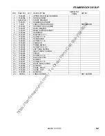
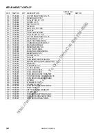
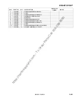
Page 17: ... 1 BACK DRAWER 8 1500215 1 REAR HOPPER GASKET 9 1500232 1 HANDGRIP 10 1500015 2 WASHER 8 X 17 11 1500014 3 SCREW 8 X 16 12 1500230 1 DASHBOARD 13 1500233 6 SCREW 6 X 16 14 1500240 1 FAIRLEAD 15 1500234 1 FRAME RWB36 16 1500182 1 SCREW 3 5 X 9 5 17 1500229 1 LEFT SIDE CASING 18 1500235 1 GRAY FRONT CASING 19 1500236 1 LEVER 20 1500098 2 SCREW 6 X 10 21 1500003 3 BLOCK NUT M8 22 1500237 1 BUMPER 23 ...

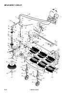
Page 18: ... 20 21 22 22 23 20 80 78 79 10 81 9 10 24 78 77 76 93 94 92 5 5 91 6 48 90 10 8 89 88 86 84 87 83 82 5 85 6 8 4 9 10 76 27 75 72 71 69 74 73 44 70 68 54 67 32 29 26 30 31 30 65 66 15 7 16 51 62 54 61 63 55 60 9 10 7 59 55 69 64 7 59 56 9 51 50 48 9 53 37 57 3635 58 33 33 33 34 49 48 47 46 42 31 38 40 39 44 43 45 41 40 40 40 40 41 39 38 31 30 30 36 37 35 24 25 27 27 26 32 31 29 28 52 ...

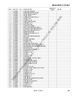
Page 19: ...R BUSHING 21 1500049 1 ROCKER PIN 22 1500055 6 SCREW 6 X 20 23 1500244 1 BRUSH ADJUSTING ARM 24 1500251 1 MAIN BRUSH ADJUSTMENT BLOCK 25 1500249 1 MAIN BROOM ADJUSTMENT BRACKET 26 1500267 4 BLOCK NUT M6 27 1500066 4 OUTER SNAP RING DIA 12 28 1500265 4 WASHER 12 X 24 29 1500264 4 SCREW 6 X 25 30 1500057 6 NUT M5 31 1500056 6 SCREW 5 X 70 32 1500263 2 SUPPORT 33 1500212 1 MAIN BROOM PPL40 16 ROW 34 ...

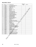
Page 20: ...1 MAIN BROOM BELT 69 1500086 2 BEARING 6005 2RS 70 1500087 1 IDLE TOOTH RING 71 1500085 1 BUSHING FOR BEARING 72 1500100 1 BEARING HK 1412 73 1500116 1 SCREW 6 X 10 74 1500256 1 PULLEY 75 1500069 2 SIDE ARMS FELT WASHER 76 1500067 4 BRUSH ADJUSTING FIXING PIVOT 77 1500243 1 BRACKET 78 1500032 3 WASHER 6 X 12 79 1500052 3 CLOCK NUT M6 80 1500252 1 PIN FOR ROCKER 81 1500266 1 PIN FOR ROCKER 82 15000...

Page 21: ...1 MAIN BROOM BELT 69 1500086 2 BEARING 6005 2RS 70 1500087 1 IDLE TOOTH RING 71 1500085 1 BUSHING FOR BEARING 72 1500100 1 BEARING HK 1412 73 1500116 1 SCREW 6 X 10 74 1500256 1 PULLEY 75 1500069 2 SIDE ARMS FELT WASHER 76 1500067 4 BRUSH ADJUSTING FIXING PIVOT 77 1500243 1 BRACKET 78 1500032 3 WASHER 6 X 12 79 1500052 3 CLOCK NUT M6 80 1500252 1 PIN FOR ROCKER 81 1500266 1 PIN FOR ROCKER 82 15000...

Page 22: ...h t t p s h a r r i s s u p p l y i n d c o m T o O r d e r P a r t s C a l l 6 0 8 2 6 8 8 0 8 0 NOTES 980200 05 28 04 5 6 ...

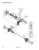
Page 23: ...00 05 28 04 5 7 51 62 26 60 61 59 58 26 28 28 29 29 53 57 51 41 63 51 56 52 52 48 48 49 50 41 55 54 51 59 47 35 34 33 17 32 31 30 44 36 16 43 17 31 46 45 37 18 32 39 29 41 42 38 40 32 38 39 29 36 37 33 31 32 1 35 34 7 21 22 30 29 22 21 29 28 28 27 26 25 24 23 22 18 22 21 20 19 18 17 14 15 16 13 12 11 9 8 7 6 5 4 3 2 10 1 ...

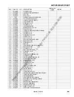
Page 24: ... 8 BLOCK NUT M8 22 1500015 12 WASHER 8 X 17 23 1500220 1 MOTOR 24 1500294 4 ANTIVIBRATIONS 30 X 20 M8 X 25 25 1500003 4 BLOCK NUT M8 26 1500141 8 SCREW 6 X 16 27 1500295 1 MOTOR SUPPORT 28 1500142 8 WASHER 6 X 18 29 1500022 6 NUT M6 30 1500115 2 WHEELS COVER DIA 200 31 1500116 3 SCREW 6 X 10 32 1500117 4 OUTER SNAP RING DIA 28 33 1500119 2 EXAGONAL BUSHING 34 1500118 2 BEARING HFL 1426 35 1500296 ...

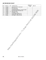
Page 25: ...PTION SERIAL NO FROM NOTES 54 1500279 1 REDUCERS TOOTHED SHAFT 55 1500275 1 KEY 5 X 5 X 20 56 1500276 1 TOOTHED GEAR 57 1500278 1 REDUCERS STRAIGHT TOOTHED GEAR 58 1500282 1 MAIN BROOM ADJUSTING RAIL 59 1500052 12 BLOCK NUT M6 60 1500283 1 WASHER 15 X 28 61 1500065 3 OUTER SNAP RING DIA 15 62 1500271 1 REDUCTION GEAR COVER 63 1500287 1 BUTTERFLY VALVE NYLON ...

Page 26: ...h t t p s h a r r i s s u p p l y i n d c o m T o O r d e r P a r t s C a l l 6 0 8 2 6 8 8 0 8 0 NOTES 980200 05 28 04 5 10 ...

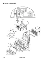
Page 27: ... r d e r P a r t s C a l l 6 0 8 2 6 8 8 0 8 0 BATTERY FILTER GROUP 980200 05 28 04 5 11 1 2 43 3 4 2 5 6 7 8A 8B 6 10 11 12 13 14 15 16 17 18 19 20 19 23 21 22 24 20 25 20 23 28 29 30 31 32 22 24 25 27 26 20 33 34 36 35 35 26 37 37 39 38 40 41 42 40 9 ...

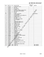
Page 28: ...175 1 PIN 17 1500176 1 INNER SNAP RING DIA 16 18 1500177 1 INNER SNAP RING DIA 16 19 1500178 2 SCREW 10 X 16 20 1500182 16 SCREW 3 5 X 9 5 21 1500208 1 LEFT SIDE FLAP 22 1500078 2 SCREW 8 X 22 23 1500181 2 INNER FLAP GRAY 24 1500310 2 BUSHING 25 1500093 2 WASHER 8 X 24 26 1500184 7 NUT M4 27 1500180 1 RIGHT SIDE FLAP GRAY 28 1500309 1 RUBBER 29 1500308 1 SQUEEGEE 30 1500183 16 SCREW 4 X 16 31 1500...

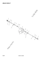
Page 29: ...h t t p s h a r r i s s u p p l y i n d c o m T o O r d e r P a r t s C a l l 6 0 8 2 6 8 8 0 8 0 BRAKE GROUP 980200 05 28 04 5 13 1 2 3 4 5 6 7 8 9 10 6 6 11 10 9 8 7 5 1 2 3 4 ...

Page 30: ...RIAL NO FROM NOTES 1 1500328 2 PARKING BRAKE BUSHING 2 1500329 2 PIVOT 3 1500330 2 PARKING BRAKE SPRING 23 4 1500331 2 SEEGER H UNI7434 DIA 6 5 1500332 2 BUSHING 6 1500333 2 PARKING BRAKE BLOCK 7 1500334 2 PARKING BRAKE PIVOT 700 8 1500335 2 PARKING BRAKE SPRING 46 9 1500336 2 PIVOT 10 1500337 1 PARKING BRAKE PEDAL SUPPORT 11 1500338 6 SCREW UNI6954 4 8 X 16 ST ...

Page 31: ... declaraciòn se refiere es conforme con las siguientes normas u otros documentos normativos EN 60204 1 EN 292 1 EN 292 2 EN 60335 1 EN 60335 2 72 EN 50106 EN 60529 EN 50081 1 EN 50082 1 EN 414 EN 45014 EN 60704 1 Teknova srl ha redacto el fasciculo tecnico sobre el presente modelo P Declaramos sob a nossa exclusiva responsabilidade que o produto ao qual esta declaração se refere está em conformida...

Reviews: