Page 9 of 22
IN052 Rev. K 0613
INSTALLATION INSTRUCTIONS
1
2
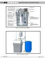
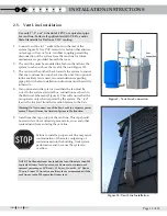
Figure 4 - Overview of Pump Installation
Over temperature warning light
Blower housing
Solenoid valves
Hammer arrester
Fail safe float
3” Cable length tether to float
(Normally closed) shuts off unit and
sounds alarm on high water level
Pump float
3” Cable length tether to float
(normally open) prevents pump dry
running
Vent
On/off float
Float switch hose clamp
Check valve (behind
pressure regulator)
Vent pipe hose clamps
Push button, thermostat override
cutout. Permits pump operation
to refill tank with cold water.
On/off float switch
housing. Aerator control
float, blower and solenoid
control (normally closed)
Thermostat switch (for over
temperature protection,
installed inside pipe cap)
Figure 5 - Plumbing Arrangement


