


IN006 Rev K 0417
5
3 Saber Way, Ward Hill, MA 01835 | radonaway.com
2.0 INSTALLATION
2.1 A.C. POWER CONNECTION
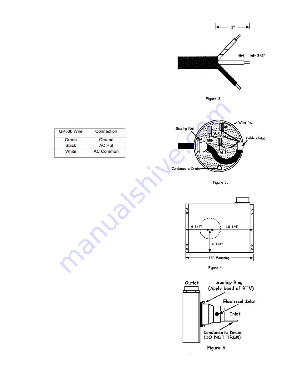
See Section 1.8. The GP500 requires an 18 gauge, 3 wire SJ
power cord, RadonAway p/n 27003 or equivalent. For proper
seal, the cord diameter should be 5/16”. To install:
1) Prepare the power cord by stripping jacket and
insulation as shown in Figure 2.
2) Loosen sealing nut on electrical inlet by turning
counterclockwise.
3) Insert power cord and route as shown in Figure 3.
4) Fasten power cord with cable clamp provided.
5) IMPORTANT: Tighten sealing nut by turning clockwise.
Hand tighting is adequate to provide seal.
6) Connect wiring with wire nuts provided, observing
proper connections:
7) Tape over wire and wire nut with electrical tape to seal
out moisture. A rubber splicing tape or self-fusing
silicone tape provide best moisture seal.
2.2 OUTDOOR (BAND JOIST OR SIDEWALL)
1) Locate site for GP500 mounting. Use the diagram in
Figure 4 to assist in locating the inlet hole for the unit.
2) Drill a 5.25” or 5.50” hole through the band joist or
sidewall.
(Use Figure 5 as a Guide for 3-6):
3) Apply a liberal bead of silicone caulk to the sealing ring.
4) Carefully feed power cord through hole and install the
unit into the hole drilled.
5) Ensure the unit is level and plumb.
6) Ensure the inlet of the fan does not contact any building
surface when mounting to avoid noise or vibration
transmission.
7) Secure unit to sidewall with four (4) #6 x 2.0” drywall
screws provided. Use nylon washers provided under the
screw heads to prevent marring the finish.
8) Complete piping run, providing flexible couplings or
other means of disconnect for servicing the unit.


