

Page 4 of 8
IN006 Rev G
1.5
CONDENSATION & DRAINAGE
Condensation is formed in the piping of a mitigation system when the air in the
piping is chilled below its dew point. This can occur at points where the system
piping goes through unheated space such as an attic, garage or outside. The
system design must provide a means for water to drain back to a slab hole to
remove the condensation.
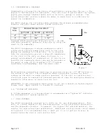
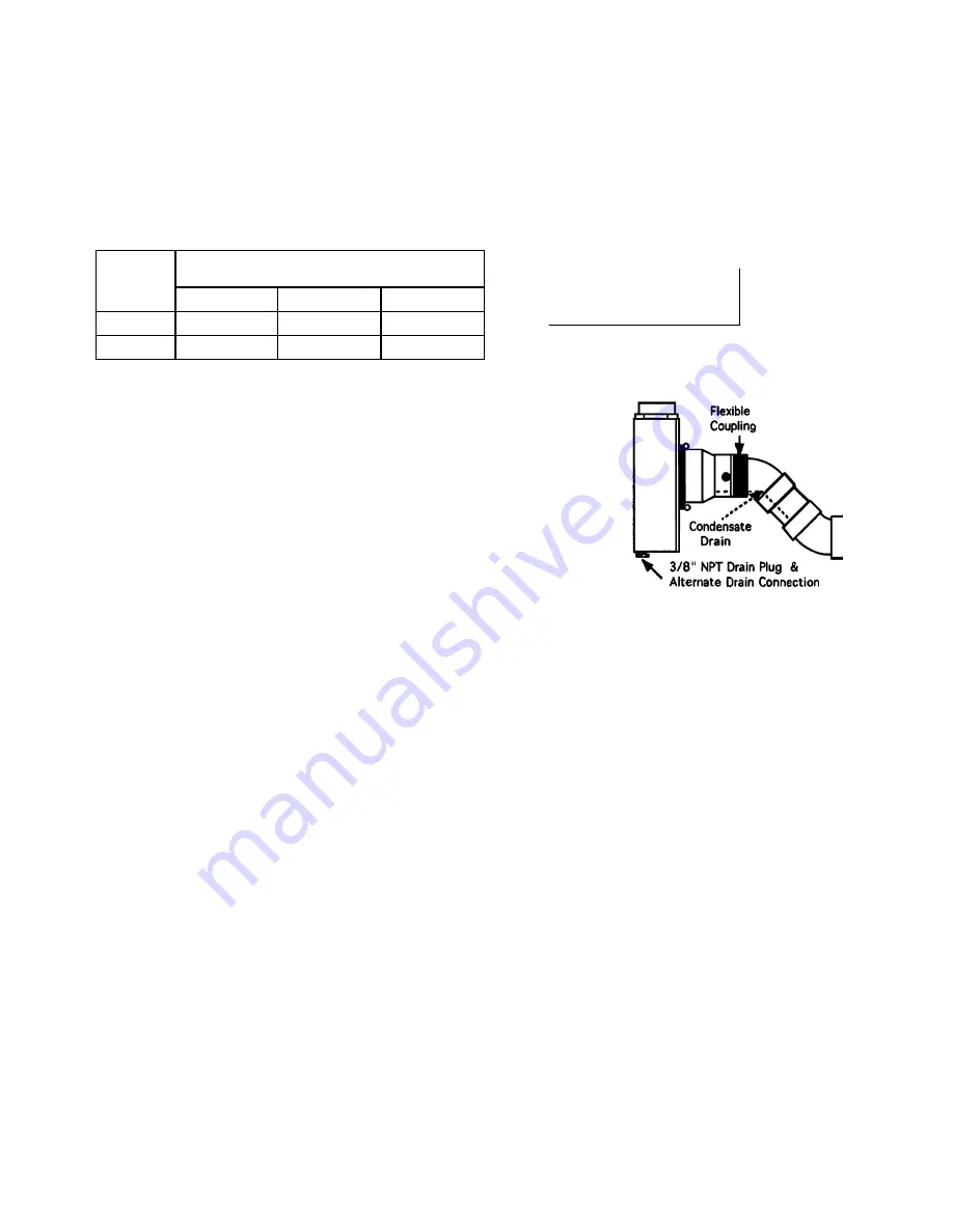
For GP500 piping, the following table provides the minimum recommended pipe
diameter and pitch under several system conditions.
Pipe
Diam.
Minimum Rise per Foot of Run*
@ 25 CFM
@ 50 CFM
@ 100 CFM
4"
1/8 "
1/4 "
3/8 "
3"
1/4 "
3/8 "
1 1/2 "
*Typical GP500 operational flow rate is 25 - 90 CFM.
(For more precision, determine flow rate by using the
chart in the addendum.)
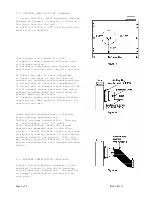
The GP500 incorporates a unique condensation drain
system which actively pumps water back to the inlet
piping for drainage to a slab hole. It is required
that the system piping provide a drop-off immediately
at the inlet of the unit, as shown in Figure 1, to
prevent reintrainment of condensation. If this is not
possible the condensate drain tube may be extended to
the point of drop off by slipping 5/16" ID tubing
(available from RadonAway) over the drain tube.
Figure 1
An alternative condensation drain may be provided using the 3/8" NPT fitting on
the bottom of the unit. The alternative drain system must account for Radon
leakage as the drain is under positive pressure. If the unit is installed and
electrical power is removed for extended periods of time the drain plug should be
removed to allow water to drain from the unit.
IMPORTANT: Do not overtighten drain plug! Do not use a wrench or tighten beyond
finger tight. Apply sealant to threads if required.
1.6 "SYSTEM ON" INDICATOR
A U-Tube manometer or a vacuum alarm is recommended as a "System On" Indicator
for affirmation of system operation.
1.7 SLAB COVERAGE
The GP500 can provide coverage up to 1000+ sq. ft. per slab penetration. This
will, of course, depend on the sub-slab material in any particular installation
and the diagnostic results. In general, the tighter the sub-slab material, the
smaller the area covered per penetration. Additional suction points can be added
as required. It is recommended that a small pit (5 to 10 gallons in size) be
created below the slab at each suction hole.
Run
Rise
Summary of Contents for GP500
Page 1: ...Page 1 of 8 IN006 Rev G ...


