background image


1. INTENDED USE 


The  MW-01-A mass  converter  is  designed  to  be  a  component of  an  industrial 
load  cell  scale.  Depending  on  the  needs,  communication  with  the  mass 
converter  can  be  carried  out  via  the  following  communication  interfaces: 
RS232,  RS485,  Ethernet,  Profibus,  Profinet,  Ethernet  IP.  The  MW-01-A  mass 
converter is compatible with indicators and PC.  


Operation  of  the  MW-01-A  mass  converter  via  PC  is  carried  out  using 

„MwManager”

 software.  


2. WARRANTY CONDITIONS 


A.  RADWAG is obliged to repair or exchange all elements that appear to be 

faulty by production or by construction.  

B.  Defining defects of unclear origin and means of their elimination can only 

be  realized  with  the  assistance  of  the  manufacturer  and  the  user 
representatives. 

C.  RADWAG  does  not  bear  any  responsibility  for  damage  or  losses 

resulting  from  unauthorized  or  inadequate  performing  of  production  
or service processes. 

D.  The warranty does not cover: 

  mechanical  damage  caused  by  product  exploitation  other  than 

intended, damage of thermal and chemical origin, damage caused by 
lightning, overvoltage in the power network or other random event, 

  inappropriate cleaning habits. 

E.  Loss of warranty takes place if: 

  a repair is carried out outside RADWAG authorized service point, 

  service claims intrusion into mechanical or electronic construction by 

unauthorized people, 

  the device does not bear security seal stickers. 

F.  Warranty  conditions  outline  the  warranty  period  for  rechargeable 

batteries attached to the device for 12 months. 

G.  For detailed warranty conditions read the service card. 
H.  Contact with the central authorized service: +48 (48) 386 63 30. 


3. MAINTENANCE 


In  order  to  clean  the  mass  converter  risk-free,  it  is  necessary  to  disconnect  
the device from the mains. 


Avoid  using  cleansers  containing  any  corrosive  chemicals,  e.g.  bleach  (with 
chlorine).  Do  not  use  cleansers  containing  abrasive  substances.  Always 
remove the dirt using a microfiber cloth, do it to avoid damage to the protective 
coating. In the case of daily maintenance: 

Summary of Contents for MW-01-A

Page 1: ......

Page 2: ...2 JANUARY 2022...

Page 3: ...l reactions The device must not be operated in hazardous areas endangered with explosion of gases and in dusty environments In the case of damage immediately unplug the device from the mains The devic...

Page 4: ...cting Load Cell s Cable Shield 13 9 FACTORY PARAMETERS 14 9 1 Factory Parameter Access 14 9 2 Factory Parameters 15 9 3 Parameter Value Modification 16 9 4 Factory Adjustment 17 9 4 1 Start Mass Deter...

Page 5: ...nty does not cover mechanical damage caused by product exploitation other than intended damage of thermal and chemical origin damage caused by lightning overvoltage in the power network or other rando...

Page 6: ...The user is NOT ALLOWED to carry out any kind of repair of the device himself herself Any attempt of module modification repair etc by unauthorized persons will result with loss of validity of manufa...

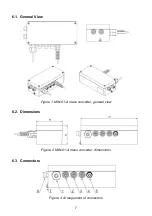
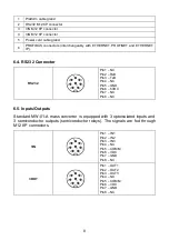
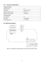
Page 7: ...7 6 1 General View Figure 1 MW 01 A mass converter general view 6 2 Dimensions Figure 2 MW 01 A mass converter dimensions 6 3 Connectors Figure 3 Arrangement of connectors...

Page 8: ...r RS232 Pin1 NC Pin2 RxD Pin3 TxD Pin4 NC Pin5 GND Pin6 5VDC Pin7 NC Pin8 NC 6 5 Inputs Outputs Standard MW 01 A mass converter is equipped with 3 optoisolated inputs and 3 semiconductor outputs semic...

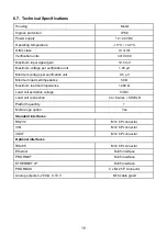
Page 9: ...tput type Solid state relay Maximum output current 0 5 A DC Maximum output voltage 30 VDC AC Input parameters Input quantity 3 Input type Optoisolated Input voltage range 5 24 VDC 6 6 Main Board Socke...

Page 10: ...cation unit 0 5 V Minimum load cell impedance 50 Maximum load cell impedance 1200 Load cell excitation voltage 5 VDC Load cell connection 4 or 6 wires SHIELD Platform quantity 1 Multi range option Yes...

Page 11: ...on a flat and even surface Keep it away from any sources of heat C Level the device Levelling procedure is to be found in TWM1 Scale user manual 7 2 START UP Plug the power supply to the mains Wait f...

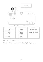
Page 12: ...l signal REMARKS E SHIELD Refer to section 8 3 REF SENSE JP2 not to be soldered REF SENSE JP4 not to be soldered IN OUTPUT IN OUTPUT EXC INPUT EXC INPUT 8 2 4 Wire Load Cell Connection Connect 4 wire...

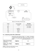
Page 13: ...erter in a metal housing connected with a platform via a load cell signal cable Scale of compact mechanical design mass converter in a metal housing connected with a platform via an extension arm etc...

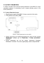
Page 14: ...r Access Plug the power supply of the MW 01 A mass converter to the mains Press internal micro switch SW1 Figure 7 Factory parameters access switch Wait for connection to be established between the ma...

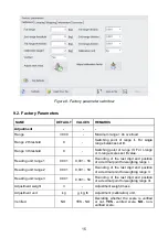
Page 15: ...001 0 001 50 Rounding of the last digit and position of a decimal point for weighing range I Reading unit range 2 0 001 0 001 50 Rounding of the last digit and position of a decimal point for weighing...

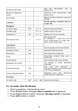
Page 16: ...quantity of converter divisions Adjustment factor 100 Adjustment calibration factor Start mass 100 Start mass value in divisions Gcor 1 Gravitational correction factor refer to section 9 6 Serial num...

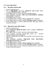
Page 17: ...o converter s memory 9 4 2 Adjustment Factor Determination Unload the weighing pan Press Determine adjustment factor button message Unload the pan is displayed Press OK button to confirm start mass de...

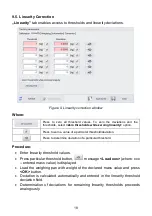
Page 18: ...lue of a particular threshold deviation Press to determine deviation of a particular threshold Procedure Enter linearity threshold values Press particular threshold button message Load xxx where xxx e...

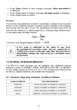
Page 19: ...scale is calibrated at the place of use then the gravitational correction value g cor parameter is 1 00000 If the scale is calibrated away from the place of use longitudinal change the value of g cor...

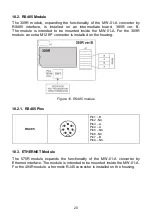
Page 20: ...the 309R module an extra M12 8P connector is installed on the housing Figure 10 RS485 module 10 2 1 RS485 Pins RS485 Pin1 B Pin2 NC Pin3 A Pin4 A Pin5 NC Pin6 NC Pin7 B Pin8 NC 10 3 ETHERNET Module T...

Page 21: ...dule combined with AB6003 module expands the functionality of the MW 01 A converter by Ethernet IP interface The module is intended to be mounted inside the indicator For the 494R module a hermetic RJ...

Page 22: ...13 495R current loop module The module s working mode is set using S1 switch when setting the module s working mode refer to the below table R1 R2 WORKING MODE 0 0 0 10 V 1 0 4 20 mA 0 1 0 20 mA 1 1 0...

Page 23: ...OLOURS Colour Signal white IOUT grey GND yellow 24V DC green GND 10 5 2 Technical Specifications Output resolution 16bit Linearity error 0 01 4 mA indication error 0 1 Temperature error for 4 mA 25 pp...

Page 24: ...ing with coding respective for the PROFIBUS standard Figure 14 PROFIBUS module 10 6 1 PROFIBUS Pin Arrangement PROFIBUS IN male Pin1 NC Pin2 A Pin3 NC Pin4 B Pin5 NC PROFIBUS OUT female Pin1 5V Pin2 A...

Page 25: ...25 Figure 15 Profinet Module 11 ACCESSORIES MW 01 A computer cable PT0020 MW 01 A Ethernet cable PT0212 MW 01 A 3IN cable PT0256 MW 01 A 3OUT cable PT0256 MW 01 A RS485 cable PT0383...

Page 26: ...26...

Reviews: