background image


PRECAUTIONS 


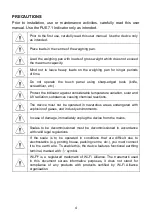
Prior  to  installation,  use  or  maintenance  activities,  carefully  read  this  user 
manual. Use the PUE 7.1 Indicator only as intended. 


Prior to the first use, carefully read this user manual. Use the device only 
as intended. 


Place loads in the centre of the weighing pan. 


Load the weighing pan with loads of gross weight which does not exceed 
the maximum capacity. 


Mind  not  to  leave  heavy  loads  on  the  weighing  pan  for  longer  periods  
of time. 


Do  not  operate  the  touch  panel  using  sharp-edged  tools  (knife, 
screwdriver, etc.). 


Protect the indicator against considerable temperature variation, solar and 
UV radiation, substances causing chemical reactions. 


The  device  must  not  be  operated  in  hazardous  areas  endangered  with 
explosion of gases, and in dusty environments. 


In case of damage, immediately unplug the device from the mains. 


Scales  to  be  decommissioned  must  be  decommissioned  in  accordance 
with valid legal regulations. 


If  the  scale  is  to  be  operated  in  conditions  that  are  difficult  due  to 
electrostatics (e.g. printing house, packing centre, etc.), you must connect 
it to the earth wire. To enable this, the device features functional earthing 

terminal, marked with 

 symbol. 


Wi-Fi

®

  is  a  registered  trademark  of  Wi-Fi  Alliance.  The  trademark  used  

in  this  document  serves  informative  purposes,  it  does  not  stand  for 
compliance  of  any  products  with  products  certified  by  Wi-Fi  Alliance 
organisation. 

Summary of Contents for WLY Series

Page 1: ......

Page 2: ...2 NOVEMBER 2020...

Page 3: ...WLY 10 D2 10kg 0 1g 195x195mm WLY 12 F1 R 12kg 0 2g 300x300mm WLY 12 F1 K 12kg 0 2g 300x300mm WLY 20 D2 20kg 0 1g 195x195mm WLY 30 F1 R 30kg 0 5g 300x300mm WLY 30 F1 K 30kg 0 5g 300x300mm WLY 60 C2 R...

Page 4: ...r and UV radiation substances causing chemical reactions The device must not be operated in hazardous areas endangered with explosion of gases and in dusty environments In case of damage immediately u...

Page 5: ...chnical Specifications 11 6 4 2 I O Schematic Diagrams 11 6 5 Operation Panel 12 7 INSTALLATION 13 7 1 UNPACKING AND INSTALLATION 13 7 1 1 WLY D2 Series 13 7 1 2 WLY C2 WLY F1 Scales 13 7 2 Levelling...

Page 6: ...ects of unclear origin and means of their elimination can only be realized with assistance of the manufacturer and user representatives C RADWAG does not bear any responsibility for damage or losses r...

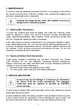
Page 7: ...r for all surfaces we recommend carrying out tests Do not use cleansers containing abrasive substances 3 2 Cleaning Stainless Steel Components Avoid using cleansers containing any corrosive chemicals...

Page 8: ...issioned must be decommissioned in accordance with valid legal regulations 6 MECHANICAL DESIGN WLY scale is a 1 load cell device intended to carry out fast and precise mass measurement of up to 120 kg...

Page 9: ...9 6 1 Dimensions Dimensions of WLY D2 scale Dimensions of WLY F1 scale Dimensions of WLY C2 scale...

Page 10: ...S232 Connector RS232 DB9 M connector male front Pin2 RxD Pin3 TxD Pin4 5 V DC Pin5 GND RS232 DSUB15 F connector female front Pin8 TxD2 Pin9 5VDC Pin10 GND Pin13 RxD2 6 4 Inputs Outputs Standard C32 sc...

Page 11: ...Technical Specifications Output parameters Output quantity 4 Output type Solid state relay Cable cross section 0 14 0 5 mm 2 Maximum output current 0 5 A DC Maximum output voltage 30 VDC Input paramet...

Page 12: ...ess to switch the scale ON OFF Press to zero the scale Press to tare the scale Press to send the weighing result to a printer or a computer Press to enter the menu function button Programmable key Pro...

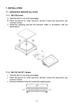
Page 13: ...en surface Keep it far away from any sources of heat C Install the weighing pan and the indicator holder in accordance with the figure below 7 1 2 WLY C2 WLY F1 Scales Take the device out of the packa...

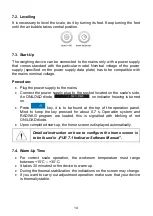
Page 14: ...diode on indicator housing is turned on Press key it is to be found at the top of the operation panel Mind to keep the key pressed for about 0 7 s Operation system and RADWAG program are loaded this i...

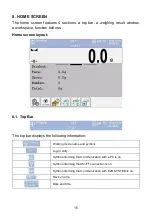
Page 15: ...buttons Home screen layout 8 1 Top Bar The top bar displays the following information Working mode name and symbol Log in entry Symbol informing that communication with a PC is on Symbol informing tha...

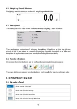
Page 16: ...mplates is currently displayed In order to switch to a different template drag the workspace screen to the left right respectively 8 4 Function Buttons On screen function buttons are to be found under...

Page 17: ...s to clear dialog box content Press to enable disable an on screen keyboard Press to read printout template saved to lb file the button becomes active upon USB flash drive connection Press to save the...

Page 18: ...void applying mechanical shocks Place the loads centrally on the weighing pan eccentricity errors are specified by EN 45501 standard point 3 6 2 In case of eccentric loading make sure that a mass of l...

Page 19: ...19 11 DIAGRAMS OF CONNECTION CABLES Scale computer cable RS232 Scale printer cable ZEBRA Scale printer cable EPSON...

Page 20: ...20 I O cable Scale Ethernet cable is a standard network cable terminated with RJ45 connectors on both ends 12 ERROR MESSAGES...

Page 21: ...21...

Reviews: