RADWIN
2000
C
Plus
User
Manual
Release
3.5.70
19
‐
6
Running
Spectrum
View
Chapter
19
If
it
is
acceptable
to
drop
the
service
click
Yes
.
The
processing
may
appear
to
have
stopped
‐
but
it
is
not
complete
until
all
of
the
Show
buttons
for
link
are
enabled.
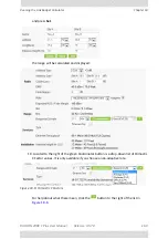
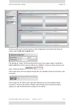
Here
is
the
result
for
the
Master:
The
keys
to
the
color
coding
is
permanently
displayed
at
the
bottom
of
the
main
window:
Figure
19
‐
1:
Spectrum
View
Analysis
color
codes
The
green
band
reflects
the
current
Master
operating
frequency.
Notice
also
the
small
fly
‐
over
diskette
icon
(circled)
to
the
upper
left
of
either
graph.
Clicking
it
opens
a
Windows
File
‐
Save
dialog
allowing
you
to
save
the
graph
to
disk
as
a
jpg
file.
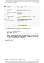
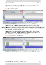
Here
is
the
analysis
for
Slave.
It
is
a
bit
different:
The
light
green
rectangle
in
the
background
of
both
antenna
displays
reflects
actual
channel
(20
MHz
wide
here)
being
used
by
the
Slave.
The
title
bar
also
contains
the
Slave’s
IP
address.
Summary of Contents for 2000 C PLUS
Page 1: ...USER MANUAL RADWIN 2000 C PLUS POINT TO POINT BROADBAND WIRELESS Release 3 5 70...
Page 17: ...Part 1 Basic Installation Release 3 5 70...
Page 139: ...Part 2 Site Synchronization Release 3 5 70...
Page 166: ...Part 3 Advanced Installation Topics Release 3 5 70...
Page 167: ...RADWIN 2000 C Plus User Manual Release 3 5 70 12 1 Chapter 12 Reserved...
Page 188: ...RADWIN 2000 C Plus User Manual Release 3 5 70 17 1 Chapter 17 Reserved...
Page 189: ...Part 4 Field Installation Topics Release 3 5 70...
Page 219: ...Part 5 Product Reference Release 3 5 70...
Page 296: ......


