RADWIN
5000
HPMP
User
Manual
Release
3.5.70
B
‐
4
DC
Power
Terminals
DC
Power
Terminals
DC
PoE
VMU
Connectors
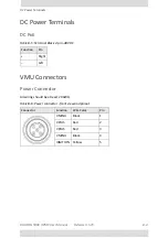
Power
Connector
All
wiring
should
be
at
least
20
AWG
.
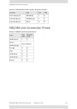
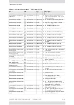
Table
B
‐
5:
Terminal
Block
2
‐
pin
‐
48VDC
Function
Pin
+
Right
–
Left
Table
B
‐
6:
Power
connector
‐
front
view
and
pinout
Connector
Function
Wire
Color
Pin
VMINU
Black
1
VPLUS
Red
2
VPLUS
Red
3
VMINU
Black
4
IGNITION
Yellow
5
Summary of Contents for 5000 HPMP
Page 1: ...USER MANUAL RADWIN 5000 POINT TO MULTIPOINT BROADBAND WIRELESS Release 3 5 70...
Page 21: ...Part 1 Basic Installation Release 3 5 70...
Page 69: ...Part 2 Sector Installation Release 3 5 70...
Page 155: ...Part 3 Sector Management Release 3 5 70...
Page 197: ...RADWIN 5000 HPMP User Manual Release 3 5 70 8 42 Nomadic...
Page 252: ...RADWIN 5000 HPMP User Manual Release 3 5 70 11 8 Registering HMUs 3 Open the Air Interface tab...
Page 290: ...Part 4 Site Synchronization Release 3 5 70...
Page 319: ...RADWIN 5000 HPMP User Manual Release 3 5 70 16 7 Configuring the GSU...
Page 320: ...Part 5 Advanced Installation Topics Release 3 5 70...
Page 354: ...Part 6 Field Installation Topics Release 3 5 70...
Page 396: ...Part 7 Product Reference Release 3 5 70...
Page 517: ......

