background image

Reinstalling/Realigning the Link 

WinLink User and Installation Guide 

Version 1.750  

6-109


Reinstalling/Realigning the Link 

It may be necessary to reinstall the link if the ODUs need to be  
realigned. 


Note: 

Activating Install Mode causes both sites to go into install mode, 

causing disruption in service for approximately fifteen seconds. 


Æ


To reinstall the link: 

1.


From the 

Configuration

 menu, choose a site. 

The Configuration dialog box opens. 

2.


In the Configuration dialog box, click the 

Install Mode

 button. 

A message box asking if you want to enter install mode appears. 

3.


Click 

Yes

 to continue. 

The system enters Install mode and the alignment tone becomes 
audible. 

4.


Realign the ODUs and start the Installation wizard (see 


Chapter

 3

). 

The Link Budget Calculator 

The Link Budget Calculator is part of the Winlink 1000 Manager 
software and is found in the Help menu. This useful utility enables you 
to calculate the expected performance of the wireless link and the 
possible configurations for a specific link range including antenna size, 
cable loss and climate conditions. 

The Link Budget Calculator enables you to calculate the expected RSS 
of the link, and determine the stability of services and their effective 
throughput as a function of the link range and deployment conditions. 

The Link Budget Calculator is found on the Installation CD and from 
tech support so it can be used prior to installation to define and verify 
link parameters such as expected RSS, maximum range, and number 
of E1s/T1s that a link is capable of providing. It enables verification of 
installation quality and provides calculations that consider “real world” 
factors such as climate.  

The Link Budget Calculator screen appears in the following figure. 

Summary of Contents for WinLink 1000

Page 1: ...WinLink 1000 Broadband Wireless Transmission System User Manual and Installation Guide Version 1 750...

Page 2: ...cense or interest shall be asserted by you with respect to such trademark You shall not copy reverse compile or reverse assemble all or any portion of the Manual or the WinLink 1000 You are prohibited...

Page 3: ...2 972 54 7586808 India Headquarters Mohan Co operative Industrial Estate E 13 B 1 Extn New Delhi 110044 India Tel 91 11 40539180 APAC Headquarters 1 Jalan Kuala 13 01 The Morningside 239639 Singapore...

Page 4: ...pment not expressly approved by the party responsible for compliance WinLink 1000 could void the user s authority to operate the equipment It is the responsibility of the installer to ensure that when...

Page 5: ...utdoor Unit ODU 2 21 WinLink 1000 Manager 2 23 All Indoor Unit AIND 2 24 TECHNICAL SPECIFICATIONS 2 25 Air Interface 2 25 Frequency Bands and Channel Bandwidth 2 25 Rates and Services Supported 2 25 R...

Page 6: ...Version Configuring BRS Channel Settings 5 75 Configuring Service Parameters 5 76 Configuring TDM Operation 5 78 Setting the Clock Configuration 5 78 Setting the T1 Line Code 5 80 Setting the TDM Back...

Page 7: ...6 121 CHAPTER 7 SECURITY 122 ENTERING AND CHANGING PASSWORDS 122 Changing the Management Password 122 Changing the Link Password 123 Forgotten Link Password 123 CHAPTER 8 DIAGNOSTICS AND TROUBLESHOOTI...

Page 8: ...SITE CONFIGURATION 13 155 CHAPTER 14 APPENDIX F BRS INSTALLATION PROCEDURE 14 158 BRS LINK ACTIVATION 14 158 BRS LINK CONFIGURATION 14 160 CHAPTER 15 APPENDIX G RF EXPOSURE 15 162 CHAPTER 16 APPENDIX...

Page 9: ...CE FOR ODU ALIGNMENT 3 41 FIGURE 3 9 LINK INSTALLATION WIZARD 3 42 FIGURE 3 10 INSTALLATION WIZARD SYSTEM DIALOG BOX 3 43 FIGURE 3 11 CHANGE LINK PASSWORD DIALOG BOX 3 45 FIGURE 3 12 TYPICAL FRONT PAN...

Page 10: ...0 THRESHOLD CONFIGURATION DIALOG BOX 6 116 FIGURE 6 11 EVENTS LOG DISPLAY 6 118 FIGURE 6 12 PREFERENCES DIALOG BOX 6 119 FIGURE 6 13 ACTIVE ALARMS SUMMARY 6 121 FIGURE 8 1 ONLINE HELP FOR WINLINK 1000...

Page 11: ...LITY TRAP MESSAGES 6 105 TABLE 6 3 EXPLANATION OF PERFORMANCE DATA 6 113 TABLE 6 4 ACTION OF THE TOOLBAR BUTTONS 6 115 TABLE 6 5 ALARMS AND INFORMATION MESSAGES 6 117 TABLE 6 6 ACTIVE ALARMS COMMAND B...

Page 12: ...ability at an affordable price Key Applications RADWIN s WinLink 1000 systems are ideally suited to meet the needs of cellular carriers service providers and private networks such as private and publi...

Page 13: ...000 service providers can expand their service footprint rapidly and affordably and provide high capacity services that match the ever growing demand for high quality high speed broadband WinLink 1000...

Page 14: ...tworks such as enterprises education government and utility organizations that want to own and control their networks and eliminate the high recurring charges for leased lines cable RADWIN s cost effe...

Page 15: ...age of the most challenging environments Figure 1 5 Multi Point to Point Video Surveillance Deployment WinLink 1000 Key Features The following represents some of the outstanding features that WinLink...

Page 16: ...e site This unique concept builds on RADWIN s Hub Site Synchronization HSS feature which synchronizes the transmission of collocated WinLink 1000 units thus virtually reducing mutual interference comm...

Page 17: ...l WinLink User and Installation Guide Version 1 750 1 17 It is recommended that you first read the Overview in the next chapter as this provides an understanding of the various parts of the system and...

Page 18: ...of a number of key components Typically each side of the link comprises an Indoor Unit IDU an Outdoor Unit ODU and an antenna A CAT5e cable from the IDU to the ODU provides both Ethernet and Power The...

Page 19: ...al unit providing two Ethernet ports 4xE1 T1 interfaces and dry contact connector alarm Figure 2 4 IDU C Front Panel IDU R A compact half 19 inch 1U plastic unit for 1 x T1 E1 backup providing in addi...

Page 20: ...Ethernet services only Power over Ethernet PoE An extremely compact device the Power Over Ethernet PoE provides Ethernet only services through one Ethernet port Figure 2 8 PoE 1 Note The PoE can only...

Page 21: ...ll The ODU connects to the IDU via a CAT5e cable ODUs are available in different frequencies and regulations in the ranges 2 3 2 7GHz 4 9 5 95GHz The ODU comes in two different form factors depending...

Page 22: ...000 WinLink 1000 High End The following table shows the differences between the systems Table 2 1 ODU Series Typical Characteristics WinLink 1000 Access WinLink 1000 WinLink 1000 High End Max Ethernet...

Page 23: ...asy to use Manager has a graphical MS Windows interface and can be utilized locally and remotely WinLink 1000 Manager provides Planning tools such as a Link Budget calculator for calculating the expec...

Page 24: ...stallation Guide Version 1 750 2 24 All Indoor Unit AIND The AIND All Indoor unit offers a single enclosure for Radio and Multiplexer modules It enables outdoor placement of only a passive element Fig...

Page 25: ...40 GHz 2 310 2 485 GHz Channel Bandwidth 5MHz 10MHz and 20MHz 5MHz Resolution Transmit Power Configurable max 23dBm Duplex Technique TDD Time Division Duplex Sensitivity dBm BER 10e 11 20MHz 87 84 80...

Page 26: ...nmental Regulations Safety EN 60950 IEC 60950 UL 60950 CAN CSA C22 2 60950 EMC EN 300 386 EN 301 489 EN 55022 EN 61000 EN 55024 AS NZS CISPR 22 CAN CSA CEI IEC CISPR 22 02 FCC 47CFR class B part 15 su...

Page 27: ...interface accepts E1 or T1 traffic supporting unframed operation E1 and T1 and AMI and B8ZS zero suppression T1 TDM services include 1 to 4 E1 T1 interfaces in the indoor units Standard E1 T1 complian...

Page 28: ...41 km 25 5 miles Up to 80 km 50 miles with an external antenna ACCESS versions up to 20 km Frequency Bands GHz 2 3 2 7GHz 4 9 5 95GHz Antennas See Antenna Characteristics in Appendix D Antenna LAN Int...

Page 29: ...wer Received by the ODU 42 to 60 VDC Power Consumption ODU plus IDU E or IDU E AL or IDU R 10W max ODU plus IDU C 14W max AIND 14 max O PoE plus ODU 25W max PoE 8 plus 8 ODU units 60W max Connector ID...

Page 30: ...b 1 5 kg 3 3 lb Environment Outdoor Unit Enclosure All weather case Temperature 35 to 60 C 31 to 140 F Indoor Unit IDU E IDU E AL IDU R and IDU C Temperature 0 to 50 C 32 to 122 F Relative Humidity Up...

Page 31: ...r 5 to 45 C 23 to 113 F IDU at a relative humidity of up to 90 non condensing Package Contents The WinLink packages include the following items ODU package containing ODU Mast Wall mounting kit plus m...

Page 32: ...ngth ordered optional O PoE package contains O PoE Mast Wall mounting kit plus mounting instructions Spare RJ 45 connector Additional Equipment Required The following is a list of the equipment requir...

Page 33: ...2 Mount the ODU at each site and antenna if external antenna is used See Mounting the ODU page 3 36 3 Connect the ODU to the IDU at both sites See page 3 37 4 Connecting the Ground to the IDU IDU C P...

Page 34: ...on Guide Version 1 750 3 34 The following diagram illustrates a typical installation of WinLink 1000 with an external antenna Figure 3 1 Typical Installation Diagram with external antenna The installa...

Page 35: ...management application is distributed on CD ROM as an executable file The application has the following PC requirements Memory 128 MB RAM Disk 1 GB free hard disk space Processor Pentium 3 or higher...

Page 36: ...anagement program in the desired location Any PC running the WinLink 1000 management application can be used to configure WinLink 1000 units Mounting the ODU The ODU is the transceiver element of the...

Page 37: ...able to the ODU RJ 45 connector If making own ODU IDU cable refer to Appendix A Wiring Specifications for the connector pin out 5 Screw in the cable glands to ensure hermetic sealing of the ODU 6 Secu...

Page 38: ...24AWG shielded cable Wiring specifications are given in Appendix A Wiring Specifications To connect the ODU to the IDU 1 Route the cable from the ODU to the IDU 2 Secure the cable along its path 3 Con...

Page 39: ...ct an 18AWG grounding cable to the grounding terminal of the device The device should be permanently connected to the ground Connecting Power to an IDU AC power is supplied to the WinLink 1000 IDU thr...

Page 40: ...onnection to the mains To maintain Overvoltage Installation Category II install a suitable surge suppressor device in the branch circuit to limit expected transients to Overvoltage Category II values...

Page 41: ...p of 180 degrees with the site A ODU so that the strongest signal from site B can be detected 5 Slowly turning the site A ODU back towards the position of Site B listen to the tone until the best sign...

Page 42: ...tivity between the management station laptop and the IDU and that the WinLink 1000 Manager application is running 2 With BRS systems you need to activate the link at both sites see Appendix F BRS Inst...

Page 43: ...x 5 Enter a SSID System ID must unique for each link in the area The SSID must include at least eight alphanumeric characters Up to 24 characters are allowed 4 Note Both sides of a link must have the...

Page 44: ...r use the alternative password supplied with the product See Changing the Link Password for more details 10 Click Next The default link with a rate of 9 Mbps is evaluated The Channel Setting dialog bo...

Page 45: ...password 7 Click OK at the successful message Note Restoring Factory Defaults returns the Link Password to wireless bridge Re Connecting the User Equipment The IDU is a standalone desktop wall mounte...

Page 46: ...router or any other compatible device to the IDU panel RJ 45 port designated LAN There may be multiple LAN ports available for connecting to different LANs depending on the IDU unit ordered Refer to A...

Page 47: ...to page 3 48 for the BRS version skip to page 3 49 WinLink 1000 with Automatic Channel Select Automatic Channel Select ACS gives WinLink the ability to change frequency channels automatically if inte...

Page 48: ...select Channel A new channel is selected from one of the Available Channels that has been defined 6 Click Next The Evaluating Rate box appears When the optimum rate for the link is selected the Servic...

Page 49: ...ion process may take a few minutes 4 If you are not satisfied with the channel that is selected automatically click Reselect Channel A new channel will be selected from one of the Available Channels t...

Page 50: ...Selecting Channels WinLink User and Installation Guide Version 1 750 3 50 Figure 3 14 BRS Channel Settings Post Transition...

Page 51: ...Services screen as shown below Notice that the Distance between the sites automatically appears in the Distance box from Version 1 600 Note WinLink ACCESS versions are Ethernet Only Figure 3 15 Instal...

Page 52: ...log box Note ACCESS versions do not have TDM services Instead ACCESS versions operate at a default rate of 2 Mbps If Ethernet Only was selected then the Finish screen appears see Figure 3 19 Installat...

Page 53: ...cover 5 Recover Internal Recover Recover Transparent Transparent WinLink transparently regenerates the clock from line clock side to Tx clock on the opposite side of the link Loop time Recover The loc...

Page 54: ...nd IDU C units it is activated after TDM service is chosen in the previous Service dialog box In Ethernet only services the TDM dialog box does not appear Setting the T1 Line Code The T1 line code can...

Page 55: ...n IDU R systems only The external equipment status is displayed on the Main screen of the Manager in IDU R systems Figure 3 17 External Equipment Status To use the Backup Mode 1 Click Enabled Backup M...

Page 56: ...Setting the TDM Backup for IDU R only WinLink User and Installation Guide Version 1 750 3 56 Figure 3 18 TDM Backup Service IDU R units only...

Page 57: ...nish Screen 3 Click Finish to complete the installation wizard Verify that the Radio Signal Strength RSS is according to expected results as determined by the Link Budget Calculator Verify that the Ra...

Page 58: ...connecting the power The PWR indicator lights up IDU E only and remains lit as long as the IDU is receiving power Controls and Indicators WinLink requires no operator attention once installed with th...

Page 59: ...disrupted LINK Green Orange Red ON Wireless link is synchronized ON During installation mode only ON Wireless link lost synchronization SERVICE Green Orange Red ON E1 or T1 line is synchronized ON Al...

Page 60: ...or short duration during startup ON for short duration during startup For normal operation after successfully connecting the ODU to the IDU ODU Green ON shows normal operation LINK Orange Green ON for...

Page 61: ...e Services Ethernet Ethernet Configuration Auto Detect Radio Link Failure Actions No action Bridge Non PoE systems Hub Mode Aging time 300 sec PoE systems Bridge Mode Community values Read write netma...

Page 62: ...5 0 0 0 For Versions 1 700 and greater any valid subnet mask may be used 4 Enter the password 1 Note The actual IP address is defined during link configuration see Defining the Management Addresses De...

Page 63: ...r read only If community values were previously defined enter them under Community in the Read Only or Read Write boxes If you are a user with read only permission click the Read Only Mode check box T...

Page 64: ...sion 1 750 4 64 Figure 4 4 WinLink 1000 Manager Main Screen Over the Air Connection indication During the login the Manager reports on over the air connection Note Over the Air connection to remote un...

Page 65: ...session make sure that a communication link between local and remote units exists The Link Status indication bar in the middle of the Main menu must be green and the Radio Link Sync message must appea...

Page 66: ...d Event log handling Set Preferences Maintenance Provides the following functions Clear counters Loopbacks System Reset Help Provides WinLink Manager Help Link Budget Calculator Get Link Information A...

Page 67: ...ys the following icons Connectivity icon showing how the device is connected to the Ethernet Network connection to the local unit using IP of the local unit Over the Air connection using IP address of...

Page 68: ...Configuration Wizard for configuration details 2 Click Next 3 Continue through the configuration wizard and define the Link name and ID Channel Rate and Services 4 Once you finish changing configurat...

Page 69: ...re defined simultaneously both sides of the link are defined simultaneously The following parameters are configured via the Site Configuration Wizard System parameters Frequency channel Air interface...

Page 70: ...750 5 70 Link Configuration Wizard Configuring System Parameters To change general parameters 1 In the Main menu click the Link Configuration button The Configuration wizard opens Figure 5 1 Configura...

Page 71: ...required to define the operating frequency channel Newer versions have a feature called Automatic Channel Select ACS This allows you to define several allowable frequency channels to which you can ch...

Page 72: ...k boxes in the Available Channels List of all the allowable channels that can be automatically selected 5 If you are not satisfied with the channel that is selected automatically click Reselect Channe...

Page 73: ...ance with ETSI unlicensed wireless data equipment is not allowed to interrupt radar services Therefore if the ETSI Version detects Radar activity it automatically changes the frequency channel This fe...

Page 74: ...o channels are defined Selecting a new channel causes the system quality to change The quality bar shows the adjustment until the system finds the best quality link Any channel selected is evaluated f...

Page 75: ...a BRS Link must be configured identically To Configure BRS Channel Settings 1 Select the Band Plan Pre Transition or Post Transition 2 Select the Bandwidth required Single Band 5MHz Double Band 10MHz...

Page 76: ...ee Figure 5 6 Ethernet data only 2 Select the transmission rate required Adaptive 9 Mbps 12 Mbps 18 Mps 24 Mbps 36 Mbps 48 Mbps The default rate is Adaptive ACCESS versions only operate in Adaptive mo...

Page 77: ...and greater distance between the sites is automatically measured If TDM services are selected then the Evaluate icon shows on the screen while the maximum rate is evaluated When evaluation is complet...

Page 78: ...IDU supports the clocking configuration feature see Figure 5 7 and Figure 5 8 A new master clock configuration option is available in the Link Configuration Wizard The automatic mode selects the clock...

Page 79: ...ervices are selected then the TDM parameters dialog box appears The TDM Parameters dialog box contains five working modes select the appropriate clock mode according to your application Choosing one o...

Page 80: ...cover Internal The remote unit internal oscillator generates the clock while the local unit recovers this clock Note The Line code option is used with T1 Systems Table 5 1 TDM Clock Modes Unit Clock M...

Page 81: ...trunk lines one for WinLink air interface via the ODU and the second external is for peripheral equipment I E PBX The external equipment status is displayed on the Main screen of the Manager in IDU R...

Page 82: ...d The Main screen is displayed Configuring the Site Editing the Configuration Parameters by Site You can edit the configuration parameters for each site individually The following functions are availa...

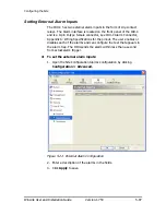
Page 83: ...nection and set the external alarm inputs Functions at the top of the dialog box Backup Save a backup ini file with the current configuration Restore Load the backup ini file created by the backup Ins...

Page 84: ...the Transmit Power Each site can have a different transmit power level To change the Transmit Power 1 Click Configuration from the main menu 2 Select which site to configure The Configuration dialog...

Page 85: ...ure 5 12 Changing the Transmit Power Defining the Management Addresses Each site must be configured separately first site A then site B To define the Management Addresses 1 Click Configuration from th...

Page 86: ...he IP address is entered in the login screen 5 Enter the Subnet Mask 6 Enter the Default Gateway 7 Enter the Trap Destination This is the IP address of the PC running the management application The ev...

Page 87: ...rotocols supported by the ODU ICMP SNMP TELNET and NTP The VLAN priority is used for the traffic sent from the ODU to the management workstation VLAN management affects all types of management connect...

Page 88: ...IP you should also configure the offset from the Universal Coordinated Time UTC If there is no server available you can either set the date and time or you can set the manager workstation time Note th...

Page 89: ...for the NTP Server click Clear and then enter the new address 5 Set the Offset value 6 To manually set the date and time click Change and edit the new values Figure 5 16 Change Date and Time HQ dialo...

Page 90: ...values Hub Mode in Hub mode the ODU transparently forwards the all the packets over the wireless link Bridge Mode In Bridge mode the ODU performs both learning and aging the aging time of the ODU is...

Page 91: ...e is configurable for line speed 10 100BaseT and duplex mode half or full duplex This mode provides an Auto detect feature where the line speed and duplex mode are detected automatically using auto ne...

Page 92: ...ttings is used To set the Ethernet information rate 1 From the Configuration menu select the site to reconfigure 2 Click Advanced Ethernet The Configuration dialog box opens 3 In the Information Rate...

Page 93: ...hoose the desired values for HQ and Remote Site After setting the new value the user must evaluate the expected quality During the evaluation the ETBE bar is displayed 5 Click Next to perform the chan...

Page 94: ...e supplied Note The manager application and the ODU use the community strings public bru1 for the local unit and public bru4097 for the remote unit These are the factory defaults but can only be used...

Page 95: ...community key can be used The alternative community key is unique per ODU and can be used only in order to change the community strings The alternative community key is supplied with the product and...

Page 96: ...ODUs are aligned and the link established It is possible to mute the tone until the alignment procedure is to be performed To mute the alignment tone 1 Click on Configuration in the Menu bar and sele...

Page 97: ...IDU C Alarm Connector Appendix A Wiring Specifications for the pinout The user enables or disables each of the alarms and can configure the text that appears in the alarm trap The ODU sends the alarm...

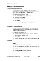
Page 98: ...which folder and under what name configuration file is to be saved and click Save Restoring a Configuration File Configuration files ini can be uploaded from the management station Verified configura...

Page 99: ...perations in the Configuration dialog box 3 Click the Restore Defaults button A message box asking if you want to restore factory default appears 4 Click the check box if you want to keep the current...

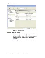
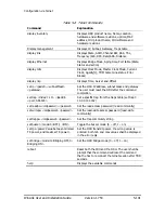
Page 100: ...ia Telnet A Telnet terminal can be used to configure and monitor the ODU on site Remote configuration cannot be performed via Telnet The login username password is identical to the communities strings...

Page 101: ...ubnet mask and gateway The user must reset the ODU after the command completion set trap index 1 10 ipaddr port 0 65535 Set a specific trap from the traps table set trap 3 10 0 0 133 162 set readpw ol...

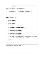
Page 102: ...help display inventory display management display link display ethernet display tdm display ntp set ip ipaddr subnetMask gateway set trap index 1 10 ipaddr port 0 65535 set readpw oldpasswd passwd set...

Page 103: ...th sides into a comprehensive file The file can be used for diagnostics and should be sent to technical support to speed up assistance The following table lists link and system information that can be...

Page 104: ...xisting networks compatibility issues may arise An incompatibility issue is indicated to the user via a change of color of the Link Status box on the Main Menu screen Trap messages in the Event Log in...

Page 105: ...ow Green restrictedCompatibility Active SW Version mismatch Magenta Same as authentic ation error SW Upgrade Recommended Yellow Magenta Same as authentication error softwareUpgradeRequired Active SW U...

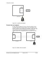
Page 106: ...cate an active loopback To deactivate a loopback From the From the Local or Remote drop down box of the Loopbacks dialog box select None and click OK A loopback is deactivated and the corresponding st...

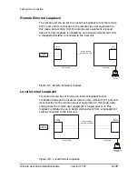
Page 107: ...et to an internal loopback to test connection between the local and remote units the local E1 T1 port and its connection to the local side user equipment In this mode data coming from the local unit i...

Page 108: ...rface T1 E1 Interface T1 Local ODU Inband Loopback Activation Command Remote ODU Figure 6 5 Remote External Loopback Local Internal Loopback The local unit can be set to close an internal loopback to...

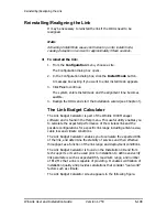
Page 109: ...ink Budget Calculator is part of the Winlink 1000 Manager software and is found in the Help menu This useful utility enables you to calculate the expected performance of the wireless link and the poss...

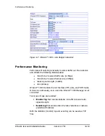
Page 110: ...n Mbps Site 1 Site 2 received frames rate in Mbps Radio signal strength in dBm Error Blocks WinLink 1000 monitors the Air interface ETH ports and TDM trunks It does so continuously even when the WinLi...

Page 111: ...ve the recorded Monitor log statistics to a text file To save the monitor log 1 From the Tools menu choose Preferences The Preferences dialog box appears Figure 6 8 Preferences dialog box 2 Click the...

Page 112: ...nd RX bytes for Ethernet For the Air Interface user defined thresholds data are collected Refer to Table 6 3 and Table 6 4 Performance Monitoring Report Toolbar Data is collected and selectively displ...

Page 113: ...be noticed For links with Ethernet only service 8 threshold is recommended and not 1 meaning that for 8 threshold the recommended BBER value should be 0 if there are no problems during the 15 min int...

Page 114: ...d4 Max RSL The maximum of the receive signal level measured in dBm Min RSL The minimum of the receive signal level measured in dBm Max TSL The maximum of the transmit signal level measured in dBm 5 Mi...

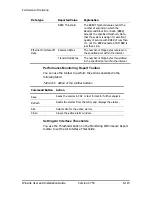
Page 115: ...ithin the interval Ethernet Interface PM Data Transmitted Bytes The number of Mega bytes transmitted in the specified port within the interval Performance Monitoring Report Toolbar You can use the too...

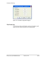
Page 116: ...and Installation Guide Version 1 750 6 116 Figure 6 10 Threshold configuration dialog box The Events Log The Events log records system failures loss of synchronization loss of signal and other events...

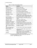
Page 117: ...during the last 20 minutes TDM Service Normal TDM service is operating properly TDM Service Alarm Error has been detected on a TDM line Configuration problem detected The link needs to be reinstalled...

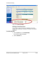
Page 118: ...splay Setting the Events Preferences You can define a color for the traps to be displayed in the Active Alarms screen according to the severity of the event The severity is predefined To set the trap...

Page 119: ...ap background color Click Background Color to change the text background To reset the trap colors Click Reset Settings to return to the default color settings Saving the Events Log You can save record...

Page 120: ...quently initiates alarms to alert the user Note To store the Event Log first define the IP address subnet mask default gateway and trap address of the management PC see Defining the Management Address...

Page 121: ...ects site for the active alarms Close Closes the active alarm window Remote Power Fail Indication Remote power fail indication indicates to one side that the other side has had a power failure The fai...

Page 122: ...nce mechanism enables the receiver to remember already received genuine messages and reject all replayed messages Initial encryption and authentication is based on a user defined master key Link Passw...

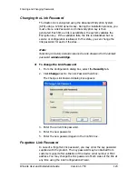
Page 123: ...e sites Note Returning to factory defaults returns the Link Password to the default password wireless bridge To change the Link Password 1 From the Configuration dialog box select the Security tab 2 C...

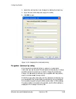
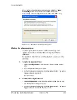
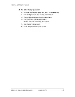
Page 124: ...ord 1 From the Configuration dialog box select the Security tab 2 Click Change next to the Link Password field box 3 The Change Link Password dialog box appears 4 Click the Forgot Link Password button...

Page 125: ...lignment reconfigure the link Verify the alignment tone sounds the Best Signal sequence The LEDs show faults in the system or the link Table 8 2 Troubleshooting with LEDs LED Status Remedy PWR Off Che...

Page 126: ...iguration using Configuration Configure site Restore Manual Configuration The new ODU can be configured manually according to the link configuration Remember to use the same settings for SSID channels...

Page 127: ...ink 1000 A WinLink 1000 has three levels of security 1 AES hardware mechanism 2 Each unit uses a unique SSID link specific code up to 24 alphanumeric characters 3 Proprietary protocol protects from ea...

Page 128: ...we need to add external arrestors on WinLink cables A Although the WinLink ODU includes arrestors and lightening protection it is suggested to implement external lightning grounding suppression See Ap...

Page 129: ...rall link site to site there is no need to travel between the two sites in order to change the configuration Easy migration between transmission channels Backup option backup and restore using ini fil...

Page 130: ...of the WinLink 1000 Manager Figure 8 1 Online Help for WinLink 1000 Technical Support Technical support for this product can be obtained from the local VAR Integrator or distributor from whom it was...

Page 131: ...tor Pinout IDU RJ 45 Color Function ODU RJ 45 1 twisted White Green Ethernet RxN 1 2 pair Green Ethernet RxT 2 3 twisted White Orange Ethernet TxT 3 6 pair Orange Ethernet TxN 6 4 twisted Blue Power 4...

Page 132: ...tive 2 TD Transmit Data negative 3 RD Receive Data positive 6 RD Receive Data negative LAN Port for PoE 8 When connecting the PoE 8 LAN port cable directly to PC a crossed LAN cable terminated with RJ...

Page 133: ...pendix A Wiring Specifications WinLink User and Installation Guide Version 1 750 133 IDU C Connectors IDU C DC Power Terminal Table 9 5 Terminal Block 3 pin 48VDC Pin Function Right Center Chassis Lef...

Page 134: ...Output 1 Normally Closed 4 Output 1 Normally Open 5 Output 2 Normally Open 6 Input 1 Negative 7 Input 2 Negative 8 Output 1 Common 9 Output 2 Common 9 COM 8 COM 7 ve 6 ve 4 3 1 2 ve Output 2 Output 1...

Page 135: ...lly Open 5 Output 2 Normally Open 6 NA NA 7 Output 2 Normally Closed 8 Output 1 Common 9 Output 2 Common IDU R and IDU AL Alarm Connectors The following table shows the pinout for the IDU R and IDU AL...

Page 136: ...1 750 136 PIN I O Description 10 Output 4 Normally Open 11 Output 4 Common 12 Output 4 Normally Common 14 Input 1 Positive 15 Input 1 Negative 16 Input 2 Positive 17 Input 2 Negative 18 Input 3 Posit...

Page 137: ...terminated with RJ 45 connectors on both ends must be used The following table shows the connector pinout Table 9 9 O POE to PC Cable Connector Pinout O PoE ETH RJ 45 Wire Color Function PC 1 wisted...

Page 138: ...Contents The ODU or O PoE mounting kit includes the following items One Large Clamp see Figure 10 1 One Small Clamp see Figure 10 2 One Arm see Figure 10 3 Four Screw hex head M8x40 Two Screw hex hea...

Page 139: ...Appendix B Mast and Wall Installation WinLink User and Installation Guide Version 1 750 10 139 Mounting WinLink 1000 on a Mast Figure 10 4 Mounting on a Mast...

Page 140: ...Appendix B Mast and Wall Installation WinLink User and Installation Guide Version 1 750 10 140 Mounting WinLink on a Wall Figure 10 5 Mounti ng on a Wall...

Page 141: ...One pivoting bracket Two metal strap clamps To install external antenna on the mast 1 Attach the U bracket to the back of the antenna using four flat washers four spring washers and four hex nuts 2 A...

Page 142: ...ctions between the two sites Prior to attempting alignment install the hardware and software in accordance with the WinLink Installation and Operation Manual The figure below shows the link setup At l...

Page 143: ...in the correct direction 2 Connect the equipment as shown in Figure 11 1 but connect a spectrum analyzer in place of the remote WinLink AIND 3 Turn on the CW transmit signal from site A from the WinL...

Page 144: ...lated in the Link Budget Calculator 2 WinLink has a unique identification number the SSID Each side of the link looks for its partner with the same SSID Therefore both sides of the link must be config...

Page 145: ...of the link move the equipment from one site closer to the other site where it is possible to actually see the antennas with the naked eye If you now get the expected receive signal level you can assu...

Page 146: ...ristics Type Gain dBi Max Range Beam width Dimensions Weight Connector Lightening Protection km miles degrees mm in Kg lb 5 8 5 4 5 3 GHz Integrated Flat panel 22 40 25 9 0 305 305 15 12 12 0 6 1 2 2...

Page 147: ...radio television and data communications The relatively short wavelength of electromagnetic radio energy at these frequencies allows reasonably sized reflectors to exhibit the very desirable highly di...

Page 148: ...all collocated ODUs this cable carries pulses sent to each ODU which synchronize their transmission with each other The pulse synchronization ensures that the transmission of packets occurs at the sam...

Page 149: ...rovides a collocation planning tool and calculator for planning the placement of multiple units at the same site It provides physical guidelines for each specific installation scenario The tool can be...

Page 150: ...ths are available for purchase The HSS is supplied with ten protective covers any port not in use must be closed with a protective cover Figure 13 4 HSS Interconnection Unit Ensure that the collocated...

Page 151: ...M all the other collocated units are Hub Sync Clients The Hub Sync Master generates the pulses that synchronize the timing of the Hub Sync Clients A Hub Sync Client can be configured to be two differe...

Page 152: ...e system is to provide see the table below Select the RFP that gives you the Best Fit for the system services and select the Channel Bandwidth accordingly The RFP must be the same for each link within...

Page 153: ...er HSM Hub Sync Client Disable Transmission HSC DT Hub Sync Client Continue Transmission HSC CT Independent Unit Synchronization N A for Master or Independent Units Synchronized for Hub Site Clients N...

Page 154: ...RFP and BW configuration Red Multiple Sources Detected More than one HSM generating pulses Incorrect configuration Red To configure the Operational States of the hub site unit 1 Click the Enabled che...

Page 155: ...ps if the system is configured with mismatches Figure 13 7 Hub Site Configuration dialog box Site Configuration For units that support HSS the Hub Site Sync option appears in the Air Interface section...

Page 156: ...inLink User and Installation Guide Version 1 750 13 156 Figure 13 8 Site Configuration Hub Site Sync dialog box The following figure is displayed when the hardware does not support HSS These units may...

Page 157: ...Appendix E Hub Site Synchronization WinLink User and Installation Guide Version 1 750 13 157 Figure 13 9 HSS Not Supported...

Page 158: ...e installation on site Both ODUs must be configured the same To Activate a BRS Link 1 Install WinLink Manager software as usual 2 When the Manager Main Screen is displayed it appears with the Link Sta...

Page 159: ...r and Installation Guide Version 1 750 14 159 Figure 14 2 BRS Air Interface dialog box 4 Set the appropriate Frequency Band Plan and Bandwidth 5 Select the required frequency band and click Apply 6 Cl...

Page 160: ...he Link Installation or the Link Configuration wizards or from the Air Interface screen Both sites in a BRS Link must be configured identically Any changes to the frequency settings cause the link to...

Page 161: ...Appendix F BRS Installation Procedure WinLink User and Installation Guide Version 1 750 14 161 Figure 14 4 BRS Channel Settings Post Transition...

Page 162: ...oduct FCC ID Antenna gain dBi Min Safety Distance cm WL1000 ODU F58 FCC INT Q3KAMWL1580 22 109 WL1000 ODU F58 FCC EXT Q3KAMWL1580 28 217 WL1000 ODU F58 FCC EXT WL1000 AIND F58 FCC EXT 4T1 Q3KAMWL1580...

Page 163: ...The utility allows you to calculate the expected RSS of the link and find the type of services and their effective throughput as a function of the link range and deployment conditions The Link Budget...

Page 164: ...ulation considering cable loss Note 3 dB 2 x Power 1W 1000 mW 10 x Log 1000 30 dBm 2W 2000 mW 10 x Log 2000 33 dBm Max Min range distance WinLink sensitivity threshold in 60dB range 30 dBm RSS sensiti...

Page 165: ...Appendix H Link Budget Calculator WinLink User and Installation Guide Version 1 750 16 165 Figure 16 2 Link Budget Screen Figure 16 3 Climate and Terrain Factor...

Page 166: ...166 Figure 16 4 Geographical Conditions Figure 16 5 Fresnel Zone Using the Link Budget Calculator The Link Budget Calculator is composed of one table where all the link parameters are defined To calc...

Page 167: ...ields in blue boxes may be edited if non standard antennas and cables are used The Fade margin is the minimum margin that is required for LOS conditions For degraded link conditions a larger fade marg...

Page 168: ...INT 2500 2690 15 22 17 5 39 5 8 9 12 WL1000 ODU HE F25 BRS EXT 2 5 2500 2690 15 22 24 45 31 6 13 WL1000 ODU F49 HP EXT 4950 4980 5 8 23 27 49 79 4 14 WL1000 ODU F49 FCC EXT 4950 4980 5 9 15 21 35 3 2...

Page 169: ...40 5835 5 0 11 22 33 2 0 36 WL1000 ODU F58 FCC EXT 5740 5835 5 4 16 28 43 20 0 37 WL1000 ACCESS F58 FCC EXT 5740 5835 5 4 16 28 43 20 0 38 WL1000 HE ODU F58 FCC EXT 5740 5835 5 4 23 28 50 100 39 WL100...

Page 170: ...ischarge path since it can not tolerate the high Lightning Current surges In order to provide an alternate Lightning Discharge path the ODU Antenna Grounding posts should be connected to Ground point...

Page 171: ...50 18 171 Internal ESD Protection circuits WinLink is designed to meet the ETSI FCC Aus NZ CSA EMC and Safety requirements To fulfill these requirements the system s Telecom lines at the ODU IDU are T...

Page 172: ...dge 5 82 community values 5 82 contact details 5 82 editing 5 82 external alarms 5 82 inventory 5 82 LAN connection 5 82 location details 5 82 management 5 82 restoring 5 98 saving 5 98 security 5 83...

Page 173: ...5 80 Link Budget Calculator overview 16 163 using 16 166 Link Compatibility 6 104 Link configuration 5 70 5 93 Link details 4 66 Link Information 6 103 Link installation 3 42 Link password 5 83 Link S...

Page 174: ...t Channel 3 48 3 49 5 72 5 74 Reset 5 98 factory defaults 5 99 Restore button 5 83 Restoring configuration 5 98 S Saving 5 98 Saving the Monitor Log 6 111 Security configuration 5 83 Service parameter...

Reviews: