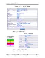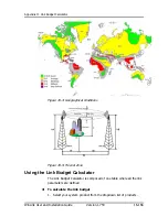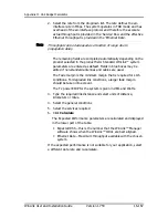
Appendix H: Link Budget Calculator
WinLink User and Installation Guide
Version 1.750
16-167
2.
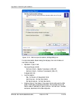
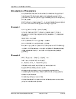
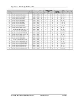
Select the rate from the dropdown list. The rate defines the air-
interface rate in Mbps. The system operates in TDD mode and has
overhead of the air-interface protocol and therefore the accurate
actual throughput is provided in the ‘Service’ Row and the effective
Ethernet throughput is provided in the ‘Ethernet Rate’.
10.
Throughput can be decreased as a function of range due to
propagation delay.
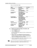
The remaining fields are completed automatically depending on the
product selected in the product field. Standard WinLink™ system
parameters are entered as default. Fields in blue boxes may be
edited if non-standard antennas and cables are used.
The Fade margin is the minimum margin that is required for LOS
conditions. For degraded link conditions, a larger fade margin
should be taken into account.
The Tx power EIRP for the system is given in dBm and Watts.
3.
Type the required link distance and select units of distance,
kilometers or miles.
4.
Select the general conditions
5.
Select the services required
6.
Click
Calculate
The Expected Performance parameters are calculated and displayed
in the lower part of the table.
y
Expected RSS – this is the number that the WinLink™ Manager
software shows when the WinLink™ ODUs are best aligned.
y
Ethernet Rate – Maximum throughput available with the chosen
system.
If the expected performance is not suitable for your application, select
a different data rate and re-calculate.
Note

