Installation
DMD2401/DMD2401L/DMD2401 IBS/IDR Satellite Modem
2-2
TM065 – Rev. 3.3
2.3 Mounting Considerations
When mounted in an equipment rack, adequate ventilation must be provided. The ambient
temperature in the rack should be between 10
°
and 35
°
C, and held constant for best equipment
operation. The air available to the rack should be clean and relatively dry. The DMD2401 units
may be stacked one on top of the other up to a maximum of 10 consecutive units before providing
a 1 RU space for airflow.
Do not mount the DMD2401 in an unprotected outdoor location where there is direct contact with
rain, snow, wind or sun. The DMD2401 is designed for indoor applications only.
The only tools required for rack mounting the DMD2401 is a set of four rack mounting screws and
an appropriate screwdriver. Rack mount brackets are an integral part of the cast front bezel of the
unit and are not removable.
Shielded cables with the shield terminated to the conductive backshells are required in order to
meet EMC directives. Cables with insulation flammability ratings of 94 VO or better are required
in order to meet low voltage directives.
The following interface connections should be available at the mounting location as a minimum:
1.
Prime AC Power.
2.
$
7UDQVPLW,)&DEOHZLWK%1&0DOH&RQQHFWRU
3.
An RS-449 Data Interface Cable with a 37-Pin Male ‘D’ Sub-Connector.
2.4 Modulator Checkout
The following descriptions assume that the DMD2401 is installed in a suitable location with prime
AC power and supporting equipment available.
2.4.1 Initial Power-Up
Before initial powerup of the DMD2401, it is a good idea to disconnect the transmit output
from the operating ground station equipment. This is especially true if the current
modulator configuration settings are unknown, where incorrect settings could disrupt the
existing communications traffic. New units from the factory are normally shipped in a
default configuration which includes setting the transmit carrier off.
Turn the unit ‘ON’ by placing the rear panel switch (above the power entry connector) to the ‘ON’
position. Upon initial and subsequent power-ups, the DMD2401 microprocessor will test itself and
several of its components before beginning its main Monitor/Control program. These power-up
diagnostics show no results if successful. If a failure is detected, the Fault LED is illuminated.
The initial field checkout of the modem can be accomplished from the front panel or in the
Terminal Mode. The Terminal Mode has the advantage of providing full screen access to all of
the modem’s parameters, but requires a separate terminal or computer running a terminal
program. The unit is placed into terminal mode by setting two options via the front panel. The two
options are the Term Baud and Emulation settings found under the System M&C submenus.
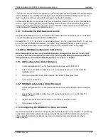
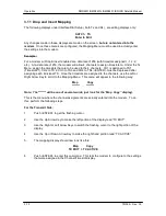
Summary of Contents for DMD2401 IBS
Page 2: ......
Page 15: ......
Page 60: ...DMD2401 DMD2401L DMD2401 IBS IDR Satellite Modem User Interfaces TM065 Rev 3 3 4 21...

