DMDVB20 LBST Satellite Modem
Theory of Operation
TM138 – Rev. 1.0
3-5
3.1.3 Tx Baseband Processing
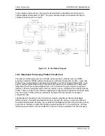
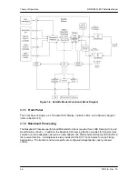
The Tx Data and Clock enters the Baseband Processor, passes through a Rate Adapting FIFO
and enters the Framer/Drop Processor. In IBS mode, the framer adds the appropriate framing as
defined in 309. The data is then sent to the Reed-Solomon Encoder.
When enabled, the Reed-Solomon Encoder, encodes the data into Reed-Solomon Blocks. The
blocks are then interleaved and synchronized to the frame pattern as defined by the selected
specification (IESS-309, DVB, etc.). After Reed-Solomon Encoding, the composite data and
clock are applied to the BB Loopback Circuit.
3.1.4 Rx Baseband Processing
The Receive Processor performs the inverse function of the Tx Processor. Data received from
the satellite passes through the LDPC Receiver to the Decoder/Deframer. The Deframer
acquires the LDPC frame, and extracts the received data, placing the data into the PD Buffer,
sending the overhead data to the UIM. The data is extracted from the buffer and is sent to the
UIM.
3.2 Monitor & Control (M&C) Subsystem
The modems M&C system is connected to most of the circuitry on any board contained in the
modem. These connections provide status on the working condition of the circuitry as well as
providing the data required for the various measurements the modem provides. The M&C
processes this information and generates status indications as well as alarms when necessary.
Detailed status information is available via the modems various user interfaces including the
remote and terminal ports. An external summary fault is available on the RS422 Data interface
The M&C contains a high-performance microprocessor and is responsible for overall command
and control of modem functions. The M&C is constantly monitoring all subsystems of the modem
by performing a periodic poll routine and configures the modem by responding to commands
input to the system. During each poll cycle, the status of each of the subsystems is collected and
reported to each of the external ports. Performance statistics such as Eb/No, buffer fill %, etc.
are compiled. If faults are detected, the M&C will take appropriate actions to minimize the effect
of such faults on the system (refer to the Fault Matrices in Section 6).
The modem supports the following M&C protocols:
Terminal Interface (Section 3.2.1)
Remote Port Interface (Section 3.2.2)
Modem Status, Alarms & Contact Closures (Section 3.2.4)
Summary of Contents for DMDVB20 LBST
Page 11: ...Table of Contents DMDVB20 LBST Satellite Modem xii TM138 Rev 1 0...
Page 14: ...DMDVB20 LBST Satellite Modem Introduction TM138 Rev 1 0 1 3...
Page 20: ...Installation DMDVB20 LBST Satellite Modem 2 6 TM138 Rev 1 0...
Page 36: ...Theory of Operation DMDVB20 LBST Satellite Modem 3 16 TM138 Rev 1 0...
Page 67: ...DMDVB20 LBST Satellite Modem User Interfaces TM138 Rev 1 0 4 31...
Page 73: ...Rear Panel Interfaces DMDVB20 LBST Satellite Modem 5 6 TM138 Rev 1 0...
Page 79: ...Maintenance and Troubleshooting DMDVB20 LBST Satellite Modem 6 6 TM138 Rev 1 0...
Page 88: ...DMDVB20 LBST Satellite Modem Technical Specifications TM138 Rev 1 0 7 9...
Page 90: ...Appendix A DMDVB20 LBST Satellite Modem A 2 TM138 Rev 1 0...
Page 97: ...DMDVB20 LBST Satellite Modem Appendix B TM138 Rev 1 0 B 7...
Page 100: ...DMDVB20 LBST Satellite Modem Appendix C TM138 Rev 1 0 C 3...
Page 107: ...DMDVB20 LBST Satellite Modem Appendix D TM138 Rev 1 0 D 7...


