background image


Page:5 


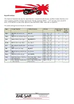
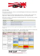
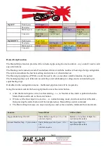
Input Functions 

The Normal Function indicates the input function in standard control mode, and the 4-button function is for 
when operating with the 4-button input mode. Polarity indicates TRUE - +12V is read as an Active/ON 
state, or if FALSE is selected, the input is sensed ACTIVE LOW- where 0V is input ON. 

The usual settings for each mode are indicated. 

Input 

Normal function


4 button function


Polarity


Normal usual 

Polartity 

4 Button 

usual 

Polarity 

High 

High

 Beam Switch Sense 

Input 

Left UP 

True – On = +12 
False – On = 0V 

Light 

Light

s On Switch Sense Input  No Connect 

True – On = +12 
False – On = 0V 

Start 

Start

er Button Sense Input 

Right DOWN 

True – On = +12 
False – On = 0V 

Brake 

Br

a

k

e Active Sense Input 

No connect 

True – On = +12 
False – On = 0V 

Left 

Left

 Indicator Switch Sense 

Input 

No Connect 

True – On = +12 
False – On = 0V 

Kill 

Kill 

Switch Sense Input 

Right UP 

True – On = +12 
False – On = 0V 

Right 

Right

 Indicator Switch Sense 

Input 

No Connect 

True – On = +12 
False – On = 0V 

Horn 

Horn

 Switch Sense Input 

Left DOWN 

True – On = +12 
False – On = 0V 

Gate 

Gate

 Sense Input – Clutch or 

Side Stand Input 

Gate Sense Input – Clutch 
or Side Stand Input


True – On = +12 
False – On = 0V


On 

Power 

On

 Input from Ignition 

– Turn Unit On 

Power Input from Ignition – 
Turn Unit On 

High + 12V on 


Summary of Contents for DRAFT D

Page 1: ...V1 0 Bike Controller Module Installation Manual DRAFT D Rae San 31 10 2022...

Page 2: ...l using the existing controls o programmable number of heat steps enable disable o Short press of start button with clutch gate switch deactivate up a step cycles around o Long press of start button w...

Page 3: ...w Most of the electronics is buried under the controller and on the underside of the bottom board The system is built on the Arduino Nano platform and the source code is open and available for downloa...

Page 4: ...t low and are pulled high when active the appropriate resistor can be snipped with a pair of side cutters to avoid the pull up function The resistors for each are labelled below If you wire the contro...

Page 5: ...Light Lights On Switch Sense Input No Connect True On 12 False On 0V T T Start Starter Button Sense Input Right DOWN True On 12 False On 0V T F Brake Brake Active Sense Input No connect True On 12 Fal...

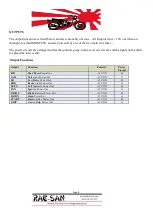
Page 6: ...circuit and the lights on the other to spread the load evenly Output Functions Output Function Polarity Power Circuit HB High Beam Power Out 12V ON B TAIL Tail Light Power Out 12V ON A LB Low Beam Pow...

Page 7: ...n 3 5s Long Press Single press more than 3 5s less than 10 0s Note that the starter and horn can be timed or toggle functions depending on the map chosen Horn Timeout 2s Starter Timeout 3s Also availa...

Page 8: ...e function if required The heated grip duty cycle talks into account the power relationship to voltage and is calculated to give equal heating steps If disabled in the configuration menu the Heated gr...

Page 9: ...mount of modulation can be set It is always a max intensity of 100 and the minimum can be set from 80 down to 0 This is needed as in particular some LED headlights will attempt to compensate and fight...

Page 10: ...te terminal program that supports ANSI sequences Putty is generally the easy choice being universally available and free Connect at 115200 8 N 1 115200 baud 8bits no parity 1 stop bit as a terminal On...

Page 11: ...evious move to the previous editable entry or Change selected Value Up or Change selected Value Down R or r Refresh redraw the screen S or s Saves the current set of values and exist edit mode Q or q...

Page 12: ...E On while Held FALSE Press is Latched TRUE TRUE FALSE KILL Input POL Hi TRUE Active on 12V FALSE Active on 0V FALSE FALSE FALSE KILL Input STATE TRUE On while Held FALSE Press is Latched TRUE TRUE FA...

Page 13: ...1 5 Number Of Flashes per Second nominal 3Hz 3 3 3 BRAKE Warning FLASH TRUE Fast Flash Brake Light when first activated to grab attention FALSE Standard Brake Light TRUE TRUE TRUE BRAKE WARN FLASH Num...

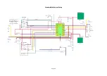
Page 14: ...Custom control Setup Easiest approach...

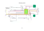
Page 15: ...Page 15 Standard Bike Control Setup...

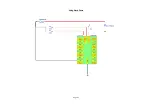
Page 16: ...Page 16 4 Button Setup Active low...

Page 17: ...Page 17 Using Stock Fuses...

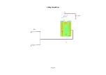
Page 18: ...Page 18 Adding Heated Grips...

Page 19: ...RAE SAN DISCLAIMS ANY RESPONSIBILITY FOR INJURIES DEATH OR DAMAGES DUE TO IMPROPER INSTALLATION OF ITS PRODUCTS ANY ACTUAL ATTORNEY FEES FOR ANY UNSUCCESSFUL CLAIM AGAINST SELLER TO BE PAID BY PLAINT...

Page 20: ...ct Rae San and or Entities Trading as Rae San prior to sending warranty product Claims for lost shipment damaged shipments or other problems regarding freight must be made directly to the responsible...

Reviews: