background image

This product may be covered by one or more of the following U.S. Patents: 
5,393,979  

5,561,344  

5,773,833  

6,225,633 

6,313,638  

6,333,632  

6,320,388 

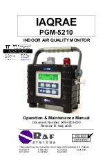
IAQRAE 

PGM-5210 

 INDOOR AIR QUALITY MONITOR 


Operation & Maintenance Manual 

Document Number: 049-4003-000 

Revision B, May 2005 


Summary of Contents for IAQRAE PGM-5210

Page 1: ...one or more of the following U S Patents 5 393 979 5 561 344 5 773 833 6 225 633 6 313 638 6 333 632 6 320 388 IAQRAE PGM 5210 INDOOR AIR QUALITY MONITOR Operation Maintenance Manual Document Number 0...

Page 2: ......

Page 3: ...fter running the monitor for several minutes the residual vapor in the detector chamber should clear and the reading should return to zero The battery of the IAQRAE Monitor will slowly drain even when...

Page 4: ...pletely before operating or servicing Any rapid up scale reading followed by a declining or erratic reading may indicate a gas concentration beyond upper scale limit which may be hazardous The calibra...

Page 5: ...ntier avant d utiliser d entretenir ou de r parer l quipement Toute lecture rapide et positive suivie d une baisse subite au erratique de la valeur peut indiquer une concentration de gaz hors gamme de...

Page 6: ......

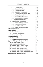
Page 7: ...2 3 2 Water Trap Filter 3 4 3 3 Remote Sampling Probe or Teflon Tubing 3 5 3 4 Calibration Adapter 3 6 4 Programming IAQRAE 4 1 4 1 Enter and Exit Programming Mode 4 3 4 2 Calibration Menu 4 5 4 2 1...

Page 8: ...Enable Disable Sensor 4 36 4 6 4 Change Custom Gas Name 4 37 5 Theory of Operation 5 1 6 Maintenance 6 1 6 1 Sensor Replacement 6 2 6 2 PID Sensor Maintenance 6 4 6 3 Sampling Pump Replacement 6 5 7...

Page 9: ...e Page 2 1 Front View Main Components 2 2 2 2 Back View Main Components 2 3 2 3 Display and Keypad 2 4 3 1 Interchangeable Battery Packs 3 3 4 1 Water bubbler connections for span cal 4 12 5 1 Block D...

Page 10: ......

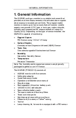
Page 11: ...Carbon Dioxide A miniature Non Dispersive Infrared NDIR Sensor Toxic Gas One interchangeable Electrochemical Sensor Humidity Capacitive Humidity Sensor Temperature Precision Thermistor Note The humidi...

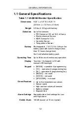
Page 12: ...ry pack with built in charger less than 10 hours charge time Six C cell alkaline battery pack Operating Time Up to 36 hours of continuous operation Display Two line 16 character LCD with manual LED ba...

Page 13: ...cc min and off Protection Password protected calibration settings alarm limits and data EM Immunity No effect when exposed to 0 43 mW cm2 RF interference 5 watt transmitter at 12 inches Data Storage...

Page 14: ...ds SO2 0 20 0 ppm 0 1 ppm 15 seconds NO 0 250 ppm 1 ppm 20 seconds NO2 0 20 0 ppm 0 1 ppm 25 seconds Cl2 0 10 0 ppm 0 1 ppm 60 seconds HCN 0 100 ppm 1 ppm 60 seconds NH3 0 50 ppm 1 ppm 150 seconds PH3...

Page 15: ...and activates alarm signals when exposure exceeds preset limits Prior to factory shipment the IAQRAE is preset with default alarm limits and sensors are pre calibrated with standard calibration gas Ho...

Page 16: ...udible Alarm Port 2 Keypad MODE operation key programming key Y operation programming key N operation programming key RADIO not used VOICE not used UP DOWN not used 3 LCD with Backlight 4 Humidity Tem...

Page 17: ...IAQRAE 1 Battery pack IAQRAE monitors are equipped with interchangeable rechargeable Lithium Ion and alkaline battery packs 2 Gas exit port 3 Charger port power jack connects IAQRAE to external DC fo...

Page 18: ...n Key Function MODE Turn power on off Choose different display mode N Toggle backlight on off Answer No Decrease values Y Alarm test and alarm acknowledgment Turn latched alarm off Turn pump on Answer...

Page 19: ...f a valid sensor is installed If a new sensor is installed a message to remind the user to calibrate the sensor will be displayed followed by a message that the alarm limits have been reset to the def...

Page 20: ...e clock will continue to operate for another 30 days When the real time clock is lost the information needs to be re entered See Section 4 5 5 Change Real Time Clock Datalog monitor versus Non Datalog...

Page 21: ...l functions listed in the round robin sequence The user also has access to Calibration Mode to calibrate or change any parameters Press MODE to access each display Start Stop Datalog will only appear...

Page 22: ...ne toxic gas sensor VOC PID sensor CO2 carbon dioxide sensor RH humidity sensor TEMP temperature sensor CO VOC CO2 R H TEMP 2 The Peak Value is the highest reading of each gas concentration since the...

Page 23: ...tomatically turns off as the battery voltage falls below 6 4 V 6 The Run Time Clock is the accumulated time in hours and minutes the monitor has been on The reading is updated in every minute and is d...

Page 24: ...omatically enters communication standby mode The Ready display will appear Connect the monitor to the serial port on a PC The monitor is ready to receive any command from the PC Press MODE again to re...

Page 25: ...30 minutes of operating time remaining before the monitor automatically turns off as the battery voltage falls below 6 4 V Alarm Signal Disabled It is extremely important to note that the alarm signa...

Page 26: ...ps flash per second Lamp Low battery 1 beep per minute Bat Memory full 1 flash per second Mem Alarm Signal Testing Under normal conditions it is possible to test the LED buzzer and backlight by moment...

Page 27: ...may be manually turned on by pressing and holding N for one second Press N a second time to turn off If N is not pressed the backlight will automatically turn off to save power The backlight will auto...

Page 28: ...3 Change Alarm Limits Sensor Cal Gas Balance Unit Low High CO2 5000 N2 ppm 5000 8000 VOC 10 Air ppm 5 00 10 Temp RH 90 Air RH CO 50 Air ppm 35 200 H2S 25 N2 ppm 10 20 SO2 5 N2 ppm 2 10 NO 25 N2 ppm 25...

Page 29: ...tube connections as short as possible Pump Duty Cycle The duty cycle function allows the user to control the time the pump is one for a specified ten second period A 70 duty cycle means that the instr...

Page 30: ...elf cleaning function is not operative when the unit is turned off and plugged into the charger Self cleaning is best performed by turning the unit on in normal operating mode setting it in a clean en...

Page 31: ...s Most of the datalogging options may be programmed from the monitor When the monitor is connected to a PC additional options may be programmed and then downloaded to the monitor There are four option...

Page 32: ...recorded in the event header followed by the measurement data Datalogging Pause Datalogging automatically pauses under the following conditions 1 Upon entering Program Mode Datalogging resumes upon ex...

Page 33: ...y pack Alkaline battery adapter Water trap filter Remote sampling probe Calibration adapter WARNING To reduce the risk of ignition of hazardous atmospheres recharge battery only in area known to be no...

Page 34: ...from fieldwork A fully charged battery powers an IAQRAE monitor for up to 36 hours continuous operation The charging time is less than 10 hours for a fully discharged battery The built in charging ci...

Page 35: ...several days the battery voltage may be low The factory supplied battery is designed for up to 36 hours of normal operation without alarm conditions or backlight usage As the battery ages or is subjec...

Page 36: ...nto the ribbed inlet port of the monitor A male Luer connector fits into the female Luer of the filter To remove the filter disconnect the Luer connector There are some vapors that are especially reac...

Page 37: ...nal 6 foot Teflon remote sampling probe with a telescoping handle is also available for hard to reach areas such as ceilings storage tanks underground manholes etc Connect the male Luer connector to t...

Page 38: ...ated with the external water trap dust filter in place The IAQRAE calibration adapter is designed to slip over the filter During calibration connect the calibration adapter to the cylinder of the cali...

Page 39: ...roRAE Suite Software Level 0 allows the user to enter Programming Mode without a password A user may still perform calibrations but has limited access to most programming functions Level 1 requires a...

Page 40: ...og Period 8 8 8 8 9 9 Select Datalog Mode 8 8 8 8 9 9 Enable Disable Datalog 8 8 8 8 9 9 Select Memory Full Type 8 8 8 8 9 9 Change Monitor Setup Change Site ID 8 8 8 8 9 9 Change User ID 8 8 8 8 9 9...

Page 41: ...ecurity Level 0 or Level 2 the monitor will enter Programming Mode and the first menu item Calibrate Monitor will display 4 Security Level 1 Enter Password 0000 will display with the far left digit fl...

Page 42: ...e monitor user operation is set to Basic level Security Level 0 the message Display Only Cannot enter will appear To Exit 1 Press MODE once 2 The display will show an instantaneous reading for normal...

Page 43: ...as as the second point of reference Zero air contains no detectable VOCs or toxic gases and is used to establish the zero point for the PID and toxic gas sensor A standard reference gas also known as...

Page 44: ...r uses dry gas 10 relative humidity as the zero gas such as dry air nitrogen or 10 ppm isobutylene The span calibration uses 90 RH gas obtained by bubbling the gas supply through pure water The temper...

Page 45: ...o air is being used attach the calibration adapter to the gas inlet port Connect the other end of the tube to the bottle of zero air If a bottle of zero air is not available place the monitor in a con...

Page 46: ...Press Y to select a sensor and N to deselect a sensor The selected sensors will have an asterisk next to the name Repeat until all sensors that need to be calibrated are selected To confirm the new s...

Page 47: ...ent sensor are not changed Cross Sensitivity Some sensors may show cross sensitivity to other gases Therefore it is important to choose the gas mixture carefully for the multiple sensor calibration to...

Page 48: ...gas flow The Apply CO Gas display will appear and the monitor will wait for the calibration gas to reach the sensor If the sensor does not detect any gas after about five seconds No gas flow will app...

Page 49: ...sks 0 CO2 press Y if CO2 free gas is being used to zero calibrate the CO2 sensor During either single or multiple sensor calibration the CO2 sensor will be calibrated to the span value defined in Sect...

Page 50: ...ylinder or ambient air through pure water See Figure 4 1 When the monitor asks 10 RH press Y if dry gas is being used to zero the RH sensor Otherwise press N to calibrate the RH sensor to span value F...

Page 51: ...ep 2 2 The sensor span value and Save will appear Use Y or N to change the digit values Press MODE to move to the next digit to the left Repeat until all digits have been entered Press MODE to move th...

Page 52: ...ied to the displayed readings 1 When the Change VOC Span Gas screen appears press Y If the VOC sensor is installed the display will show the span gas name If the VOC sensor is not installed the No VOC...

Page 53: ...To advance to step 3 press Y otherwise press N to accept the previously stored alarm limits and move to the Change High or Low Alarm Limit submenu CO High Limit 450 Save CO Low Limit 200 Save 3 To mo...

Page 54: ...interval The user may review these stored readings change the datalog setup or program additional datalog options by downloading from PC to IAQRAE using ProRAE Suite software The Change Datalog Settin...

Page 55: ...og memory This does not change peak or minimum concentration or run time values stored in other locations 1 When the Clear All Data screen appears press Y to clear the data memory The monitor will sho...

Page 56: ...iod 60 will appear 60 is the previously stored datalog period 2 To modify this period press MODE to move to the far left digit and use Y or N to change the value Press MODE to advance to the next digi...

Page 57: ...et moment Automatic Datalogging is automatically started whenever the monitor is turned on Manual The user must start Datalogging by toggling to the Start Datalog menu in the main menu loop 1 When the...

Page 58: ...he monitor All previously selected sensors enabled for Datalog are marked with an asterisk The cursor will be blinking on OK CO VOC CO2 RH OK Temp 2 Press MODE to move from one sensor location to the...

Page 59: ...nce the memory is full The Wrap Around selection overwrites the oldest data as the monitor continues datalogging 1 When the Select Memory Full Type screen appears press Y to see the current selection...

Page 60: ...enter user information for the IAQRAE monitor The Monitor Setup submenus are listed below Change Site ID Change User ID Change Alarm Mode Change User Mode Change Real Time Clock Change Light and Buzz...

Page 61: ...D Site ID xxxxxxxx Press MODE to move the cursor to the left most digit 2 Press Y or N to cycle through all 26 letters and 10 numerals Hold down Y or N for rapid scrolling Press MODE to advance to the...

Page 62: ...D User ID xxxxxxxx Press MODE to move the cursor to the left most digit 2 Press Y or N to cycle through all 26 letters and 10 numerals Hold down Y or N for rapid scrolling Press MODE to advance to the...

Page 63: ...falls below the lower alarm limit In Latched mode the alarm remains on even after the alarm condition no longer exists The alarm must be turned off by pressing Y 1 When the Change Alarm Mode screen a...

Page 64: ...Mode limits access to certain Calibration and Monitor Setup functions See Table 4 1 for a detailed list of functions accessible in the two modes 1 When the Change User Mode screen appears press Y and...

Page 65: ...rrent date and time 16 Apr 02 04 52 Press MODE to move the cursor to the date 16 Apr 02 15 24 Save 2 To modify the date and time use Y or N to change the digit value and press MODE to advance to the n...

Page 66: ...r needs The factory default setting is saved to have both the light and buzzer turn on during alarm conditions 1 At the screen Change Light Buzzer Mode press Y to view the submenus 2 Press N to scroll...

Page 67: ...ow the current password Password 0000 Save 2 Press MODE to move the cursor from Save to the left digit Press Y or N to cycle through all 10 numerals Press MODE to move to the next digit Repeat until a...

Page 68: ...nds and then turns the pump off for three seconds See Section 2 9 Integrated Sampling Pump Pump Duty Cycle for more information 1 At the Change Duty Cycle screen press Y and the following will appear...

Page 69: ...or Spanish Additional languages may be added in the future 1 When the Change Display Language screen appears press Y to display the current Language Display Language English 2 Press N to toggle betwee...

Page 70: ...The user may set the temperature unit to either Fahrenheit to Celsius factory setting 1 At the Temperature Unit Celsius display press N to toggle between Fahrenheit and Celsius 2 Press Y or MODE to a...

Page 71: ...measurement gas CF __________________________________ Sensitivity to isobutylene calibration gas When the monitor is calibrated to isobutylene but used to measure another compound the CF is multiplie...

Page 72: ...lay the equivalent concentration of the selected VOC gas 1 When the Change VOC Gas measurement screen appears press Y If a PID sensor is installed and enabled the following display will appear VOC gas...

Page 73: ...rrent correction factor Correction Factor 100 Save 2 Press MODE to move the cursor from Save to the left digit Press Y or N to cycle through 10 numerals Press MODE to advance to the next digit on the...

Page 74: ...s Y The display will show all the sensors installed in the monitor An enabled sensor is marked with an asterisk a disabled sensor will have no asterisk The cursor will blink at the OK message CO VOC C...

Page 75: ...he cursor from the to the second line Custom Gas Custom Gas Save Custom Gas 2 To change the custom gas name press Y or N to scroll through the list of letters Use MODE to advance the cursor 3 To save...

Page 76: ......

Page 77: ...sor measures inorganic toxic gases Humidity is measured with a polymer capacitate sensor and temperature with a Thermistor in a combined by a humidity temperature HT sensor Microprocessor LCD Display...

Page 78: ...PC A two line by sixteen character LCD is used to show the readings The user interacts with the monitor by using the Y key N key and MODE key on the front membrane panel A rechargeable Lithium Ion bat...

Page 79: ...SENSOR AND PUMP MAINTENANCE 6 1 6 Maintenance Figure 6 1 Internal Structure of IAQRAE...

Page 80: ...s sensor socket allows the user to plug in any of the toxic gas sensors offered by RAE Systems Note The firmware recognizes all sensors except the ClO2 sensor 1 Turn the IAQRAE off 2 Disconnect the ba...

Page 81: ...a pin jumper located on the edge of the analog PCB next to the bottom of the housing When an NO or NH3 sensor is plugged into the sensor socket it is necessary to switch the jumper to enable the bias...

Page 82: ...owest value 50 to allow the maximum self cleaning IAQRAE has a built in sensing mechanism to monitor the status of the UV lamp If the UV lamp is not on the Lamp error message will appear To resolve th...

Page 83: ...lly unscrew four No 2 screws that hold down the gas piping plate to the analog PCB and sensors Remove the gas piping plate 3 Carefully loosen the connector Unscrew the two screws that hold the pump as...

Page 84: ......

Page 85: ...Mode and refers to the table in Section 7 2 the problem can usually be narrowed down and corrected without having to return the monitor for repair WARNING The diagnostic mode allows the user to set se...

Page 86: ...the special mode start up the display will show 1 to 5 numbers with a message Raw These numbers are raw sensor readings without calibration Other critical parameters of the monitor are available as s...

Page 87: ...spond and the raw reading should increase or decrease If the reading of the corresponding sensor does not change when the specific gas is applied then the sensor may be defective 365 360 2373 530 RAW...

Page 88: ...s is applied CO2 should read a lower value while Ref should display almost no change When a CO2 gas is applied CO2 output should increase The bias value is adjustable but should not be changed CO2 REF...

Page 89: ...t row Pump xxx zzz The current pump stall value is displayed on the second row Stall yyy The typical maximum pump current without any blockage should be between 20 35 when the speed is set to be low a...

Page 90: ...ally refreshed 8 Clock and Battery Voltage This display shows the real time clock and battery voltage in raw count 9 Battery Duration Time This display shows the run time of the last time the unit pow...

Page 91: ...authorized service center Lost password Forgot password Call authorized service center Buzzer inoperative Defective buzzer Call authorized service center Reading abnormally high Wrong calibration data...

Page 92: ...Do fresh air calibration Wait for reading to be stabilized Reading jumps around randomly Incorrect gas calibration Low sensitivity to calibration gas Calibrate the sensor Reduce duty cycle to clean P...

Page 93: ...scale PID measurement in humid environment Dirty or wet sensor Run dry gas through sensor Reduce pump duty cycle to clean sensor Replace water trap filter VOC measurement saturates at certain level D...

Page 94: ......

Page 95: ...5 seconds If the unit is turned on in Diagnostic Mode the user may switch between Diagnostic Mode and Normal Mode by pressing MODE and Y together Normal Mode M Y Diagnostic Mode Instrument Off Normal...

Page 96: ...X XXXX MIN XXXX Battery 7 4V Shut off at 6 4V Jun 21 01 13 15 ON 00 00 Start Stop Datalog Communicate with PC VOC gas Isobutylene M M M M M M Y M M N M Reset Peak and Min Y N M N Y Normal Mode Availab...

Page 97: ...Bias xxx xxx xx Contrast xxx 000 255 Pump 18 16 Stall xx Mar 1 02 15 36 Battery xxx 25C Battery duration 33 21 Communicate with PC M M M M M M M M M M M N Y next gain N previous gain Y N Y increment...

Page 98: ...brate Monitor Fresh Air Calibration Multiple Sensor Calibration Single Sensor Calibration Modify Span Gas Value Change VOC Span Gas Y N N N N N N Process Process Process Process Y Y Y Y Y Process M Ba...

Page 99: ...APPENDIX A A 5 Programming Mode Alarm Limit Menu Change Alarm Limit Change High Alarm Limit Change Low Alarm Limit Y N N M Y Y N Process Process Back to User Mode M Alarm Limit Menu To Datalog Menu...

Page 100: ...hange Datalog Setting Clear All Data Change Datalog Period Select Datalog Mode Enable Disable Datalog Y N N N N N M Y Y Y Y Select Memory Full Type Y N Process Process Process Process Process Back to...

Page 101: ...r Mode Change Real Time Clock Change Light and Buzzer Mode Change Password Change Pump Duty Cycle Change Display Language Y N N N N N N N N N M Y Y Y Y Y Y Y Y Y N Set Temperature Unit Y N Process Pro...

Page 102: ...uration Menu Change Sensor Configuration Change VOC Gas measurement Y N N N Y Y Y M Process Process Process Back to User Mode M Sensor Config Menu To Calibration Menu Enable Disable Sensor Edit Correc...

Page 103: ...play the correct gas reading Make sure the name of the measurement gas and calibration gas are entered correctly See Section 4 6 2 Edit Correction Factors If the correction factor of the gas is 1 0 th...

Page 104: ...Octane n 1 8 Hexane n 4 3 Pentane 8 4 Hydrazine 2 6 Perchloroethene 0 57 Hydrogen NR Pinene 0 31 Hydrogen sulfide 3 3 Pinene 0 37 Isobutane 100 Propane NR Isobutene 1 00 Propene 1 4 Isobutyl acrylate...

Page 105: ......

Page 106: ...2878 Tubes Sales 888 RAE TUBE 888 723 8823 Technical Support 888 723 4800 E mail RaeSales raesystems com Tech raesystems com Website www raesystems com Important Note Before returning the unit for ser...

Reviews: