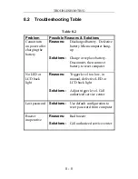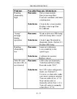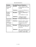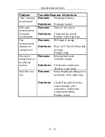
TROUBLESHOOTING
8 - 6
5) DAC Output Counts
The menu allows the user to adjust the value of the analog
output DAC use the
[Y/+]
and
[N/-]
keys. The remote alarm
output signal on the serial interface cable is deselected and the
analog output signal is selected in its place. This signal has a
range of 0 to 2.5V in 4096 steps. The initial default output is
2048, or half-scale. See Figure 8-1 for signal pin-out. The
DAC output is linearly proportional to concentration.
6) Alarm Test
This menu is used to test the monitor’s alarm generators,
including four bright LED’s, the loud buzzer, and the vibrator
output signal (remote alarm). The message “Alarm” is first
displayed, followed by “On?” If the
[Y/+]
key is pressed at this
point, the alarms will turn on and the message “Off?” will
appear. To turn the alarms off, press the
[Y/+]
key again.
Check external alarm signal at connector.
Figure 8-1 Communication/Alarm Connector
7) Adjust Backlight Threshold
This display can be used to calibrate the LCD backlight turn on
and off threshold. Use the following steps to adjust the
backlight threshold.
1. The “Lite = xxx” message displays the present ambient light
level incident on the face of the monitor. In a brightly lit
room, the light reading should be above 130.
(front view of connector on monitor
)
Pos 1, Ground
(female, hole) Black
Pos 2, Alarm/DAC
(female, hole)
Pos 3, Receive
(male, pin) Red
Pos 4, Transmit
(male, pin) Green


