background image

4 / 12

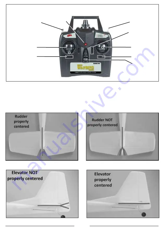
Transmitter Layout


PASS  Switch

LED Indicator

One-key Stunt Button

Throttle/Rudder

Rudder Trim

Elevator Trim

Aileron/Elevator 

Aileron Trim

ON/OFF Switch

With the transmitter turned on and the battery conected to the ESC (and installed in the 

battery compartment), it is now possible to check the center of all control surfaces.

Check that the rudder is properly centered as shown above.

Then check that the elevator is properly centered as shown above.

NOTE: Turn the PASS switch off (expert mode) before you complete the steps 

below. See more information in "PASS System" section.

Centering Control Surfaces

Summary of Contents for MICRO WARBIRD Series

Page 1: ...Manual P 51D Mustang P 51D Mustang F4U Corsair F4U Corsair T 28 Trojan T 28 Trojan...

Page 2: ...or property damage Ensure that batteries are properly charged before flying If at any time that battery begins to balloon or swell discontinue use immediately Always store batteries at room temperatur...

Page 3: ...USB adapter 3 Connect battery to the charger 4 The charging process will take up to 3 hours As a safety precaution never charge the battery for longer than 4 hours While charging the red LED indicato...

Page 4: ...ery conected to the ESC and installed in the battery compartment it is now possible to check the center of all control surfaces Check that the rudder is properly centered as shown above Then check tha...

Page 5: ...trol Full Assist switch toward pilot In this position the bank and dive angles of the airplane are greatly restricted and the plane will return to level flight when the sticks are released Partial Ass...

Page 6: ...craft power on and the PASS system in Expert check the elevator rudder and aileron response as shown above With the aircraft power on and the PASS system in Partial or Full Assist check the elevator r...

Page 7: ...s only required if the model is not performing properly when in PASS mode Perform this with the airplane held in a level flying position The stunt button allows the pilot to perform a roll or loop aut...

Page 8: ...eed a Phillips screwdriver and needle nose pliers not included 1 Remove screw with a Phillips screwdriver and remove the spinner and propeller 2 Remove shaft adaptor labeled base on the diagram If it...

Page 9: ...lobally Unique Identifier code of a single specific transmitter When a receiver is bound to a transmitter the receiver will only respond to that specific transmitter Binding Instructions If you need t...

Page 10: ...28 Trojan Item Number Description RGRA1302 Micro T 28 Trojan RTF RGRA1323 Prop Spinner Set F4U T 28 RGRA1324 Fuselage T 28 RGRA1325 Main Wing and Tail T 28 RGRA1326 Pushrod Set T 28 RGRA1327 Landing...

Page 11: ...R C Proof of purchase is required for all warranty claims SERVICE OR REPLACEMENT AS PROVIDED UNDER THIS WARRANTY IS THE PURCHASER S SOLE AND EXCLUSIVE REMEDY Limitation of Liability RAGE R C SHALL NO...

Page 12: ...2021 HRP Distributing Inc...

Reviews: