59
g.
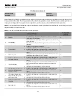
Fuel Pump
•
Inspect component for leaks, damage, or excessive wear.
•
Inspect Clamps: Ensuring proper fit, note leaks, damage, or
excessive wear.
•
Inspect Lines: Check for dry rot and chaffing.
g.
h.
Carburetor
•
Inspect component for leaks, damage, or excessive wear.
•
Inspect Clamps: Ensuring proper fit, note leaks, damage, or
excessive wear.
•
Inspect Lines: Check for dry rot and chaffing.
h.
i.
Primer
•
Inspect for damage due to corrosion, lack of maintenance, or
abuse. Loose ball joints, locknuts, bent link rods, loose rod snaps.
•
Lubricate with Friction Surface Marine Grease.
i.
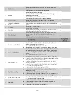
Operational Checks
Completed
(initial)
a.
Pull Start
•
Start the motor using the recoil starter.
a.
b.
Electric Start
•
Start the motor using the electric start push button.
b.
c.
Neutral Safety
•
Verify that the motor will not start in gear both forward and
reverse.
c.
d.
Water discharge from
check ports
•
When the motor is running verify that water is being discharged
from all check ports.
d.
e.
Tiller Steering
•
When moving the Tiller Arm, verify that the motor moves freely
to port and starboard.
e.
f.
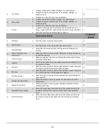
Neutral
•
Verify the propeller does not engage when the gear selector is in
the neutral position.
f.
g.
Forward
•
With the motor at idle, verify the Gear Selector moves freely into
the forward position and the propeller engages.
g.
h.
Reverse
•
With the motor at idle, verify the Gear Selector moves freely into
the reverse position and the propeller engages.
h.
i.
Throttle Control
•
With the engine in neutral, slowly increase the throttle RPM’s to
approximately.
i.
j.
Emergency Stop Switch
•
While the motor is running, remove the lock plate, the motor
should stop.
j.
k.
Engine Stop Switch
•
While the motor is running, press the Engine Stop Switch, the
motor should stop.
k.
l.
Shallow Water Running
•
Move the motor Reverse Lock Lever to the release position, lift
the lower unit past a 45° angle until the tilt stopper assembly
locks.
l.
m.
Full Tilt Position
•
Move the motor Reverse Lock Lever to the release position, lift
the Lower Unit past a 90° angle until the tilt stopper assembly
locks.
Summary of Contents for Raider 40 HP
Page 1: ...i ...
Page 2: ...ii This page intentionally left blank ...
Page 65: ...56 APPENDICES ...
Page 69: ...60 Notes and Discrepancies ...
Page 72: ...This page intentionally left blank ...
Page 73: ......

