background image


SERVICE MANUAL 


Two stroke Low pressure 


Direct Injection (TLDI) 


Multi-fuel  


Submersible 


This manual has been prepared for the United States Guardian Angels for 

service of the Multi-fuel, Submersible Outboard motor designed and manufactured 

under Contract No. N61331⑩11⑩C-0008, dated 3/4/11.  The data presented in this 

manual was revised as of August 2013 representing the latest revision. 


August 2013 

Summary of Contents for 40 hp

Page 1: ... has been prepared for the United States Guardian Angels for service of the Multi fuel Submersible Outboard motor designed and manufactured under Contract No N61331 11 C 0008 dated 3 4 11 The data presented in this manual was revised as of August 2013 representing the latest revision August 2013 ...

Page 2: ...otors Parts can be found worldwide common with these three motors This manual This manual This manual This manual represents the production version of represents the production version of represents the production version of represents the production version of the Raider the Raider the Raider the Raider outboard motors Both outboard motors Both outboard motors Both outboard motors Both outboards ...

Page 3: ......

Page 4: ...pter 5 Installing and Inspecting Electrical Components Chapter 6 Disassembling Inspecting and Reassembling Lower Unit Chapter 6 Disassembling Inspecting and Reassembling Lower Unit Chapter 6 Disassembling Inspecting and Reassembling Lower Unit Chapter 6 Disassembling Inspecting and Reassembling Lower Unit Chapter 7 Installation Chapter 7 Installation Chapter 7 Installation Chapter 7 Installation T...

Page 5: ...NG BATTERY SYSTEM 3 12 CHAPTER 4 DISASSEMBL CHAPTER 4 DISASSEMBL CHAPTER 4 DISASSEMBL CHAPTER 4 DISASSEMBLING INSPECTING AND ING INSPECTING AND ING INSPECTING AND ING INSPECTING AND REASSE REASSE REASSE REASSEMBLING POWER UNIT MBLING POWER UNIT MBLING POWER UNIT MBLING POWER UNIT 4 4 4 4 1 1 1 1 1 POWER UNIT 4 2 2 PERIPHERAL PARTS 4 7 3 FUEL SYSTEM 4 25 4 THROTTLE MECHANISM 4 37 5 DISASSEMBLING EN...

Page 6: ... DEWATERING VALVES THE OPERATOR MUST OPEN AFTER SUBMERSION 9 2 2 DE WATERING PROCEDURE 9 3 CHAPTER 10 TROUBLESH CHAPTER 10 TROUBLESH CHAPTER 10 TROUBLESH CHAPTER 10 TROUBLESHOOTING OOTING OOTING OOTING 10 10 10 10 6 6 6 6 1 TROUBLESHOOTING TABLE 10 7 2 TLDI SELF DIAGNOSING FUNCTIONS 10 19 CHAPTER 11 SERVICING CHAPTER 11 SERVICING CHAPTER 11 SERVICING CHAPTER 11 SERVICING 11 11 11 11 1 1 1 1 1 GENE...

Page 7: ...er 1 Specifications Specifications Specifications Specifications 1 SPECIFICATIONS TABLE 1 1 2 OUTLINE DIMENSIONS 1 2 3 WHAT IS TLDI 1 4 4 FUEL SUPPLY SYSTEM 1 7 5 AIR SUPPLY SYSTEM 1 8 6 OIL SUPPLY SYSTEM 1 9 1 ...

Page 8: ...Scavenging system 5 port loop Charge Exhaust system Through hub Lubrication system Oil injection Cooling system Water cooling Water temperature control Thermostat with pressure relief valve Ignition System Inductive Ignition timing control Electronics Control Unit ECU Firing Order 1 2 3 Spark Plug NGK PZFR6H Alternator 12V 280W Maximum Battery Not required option available under cowling Trim Angle...

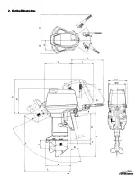
Page 9: ...1 2 2 O 2 O 2 O 2 Outline Dimensions utline Dimensions utline Dimensions utline Dimensions ...

Page 10: ...in C Transom L 530 mm 20 9 in Transom UL 657 mm 25 9 in D 568 mm 22 4 in E 680 mm 26 8 in F 85 mm 3 3 in G 600 mm 23 6 in H 520 mm 20 5 in I 440 mm 17 3 in J 31 70mm 1 2 2 8 in K 490 mm 19 3 in Transom 5 800 mm 31 5 in L Transom L 910 mm 35 8 in Transom UL 1025 mm 40 4 in Ml 384 mm 15 1 in M2 345 mm 13 6 in N 310mm 12 2 in 0 235 mm 9 3 in P 565 mm 22 2 in Q l2odeg R l2deg S 35deg T 75deg U 161 mm ...

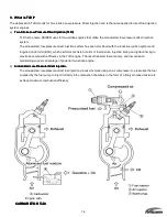
Page 11: ... system and Engine Control Unit ECU which performs precision control of fuel mixture injection timing and ignition timing to maximize combustion efficiency in the TLDI engine The result is better fuel economy and low emission maintaining superior advantage of powerful two stroke engine b Air Air Air Air Assisted Low Assisted Low Assisted Low Assisted Low Pressure Direct Injection Pressure Direct I...

Page 12: ... allows the Raider 50 horsepower outboard to function as a multi fuel engine Input Control Input Control Input Control Input Control Sensor Switch Control Control Control Control ECU Output Output Output Output Actuator Throttle Position Sensor TPS 1 2 3 Fuel injectors Crank Position Sensor CPS 1 2 3 Air injectors Water Temperature Sensor 1 2 3 Ignition coils Oil level Sensor Fuel Selector Capacit...

Page 13: ...sor CPS Position Sensor CPS Position Sensor CPS Position Sensor CPS Crank position sensor is designed to sense the encoder located above the ring gear on the flywheel in order to detect crankshaft position and transmit s the information to the ECU Water Water Water Water Temperature Sensor Temperature Sensor Temperature Sensor Temperature Sensor Positioned on the water jacket installed on the cyli...

Page 14: ... injected into the combustion chambers The fuel regulator 8 regulates fuel pressure so as to keep it 70 kPa 10 psi higher than the pressurized air pressure 55OkPa Bopsi to inject fuel into combustion chamber after overcoming the air pressure mentioned in Air supply system as follows Any excess fuelis depressurized and diverted through the FFP case 9 and back to the vapor separator 4 The returned f...

Page 15: ...ugh the air filter 1 and sends compressed air through to the air rail 3 The air regulator 4 regulates air at the optimum combustion pressure of 550 kPa 80 psi and the regulated air is injected into engine combustion chamber together with pressurized fuel Any excess air is depressurized and discharged into exhaust gas 5 from the bottom of the cylinder ...

Page 16: ... 2 air box 5 3 air box 6 and the air compressor 7 Ports 4 5 and 6 serve to lubricate the engine pistons while port 7 lubricates the air compressor TLDI includes an oil recirculation system in which the excess oil from the air compressor 7 is diverted to 3 crankcase 8 for use in lubricating the drive gear of oil pump 1 Any oil left over from there is diverted to crank upper bearing and 1 crankcase ...

Page 17: ...1 10 ...

Page 18: ... Information 1 GENERAL PRECAUTIONS FOR SERVICING 2 2 2 2 1 1 1 1 2 SPECIFICATIONS AND STANDARDS USED IN SERVICING 2 2 2 2 3 3 3 3 3 LISTS OF POINTS FOR APPLYING SEALANT ADHESIVE AND LUBRICATION 2 2 2 2 9 9 9 9 4 TORQUE TABLE 2 2 2 2 15 15 15 15 5 SPECIAL TOOLS 2 2 2 2 16 16 16 16 2 2 2 2 2 ...

Page 19: ...2 2 ...

Page 20: ...2 1 ...

Page 21: ...k in their original locations 8 As normal practice check disassembled parts for any wear or damage by first wiping them clean then washing them in solvent 9 With reassembly operations it is essential to observe precise detail in centering vacuum sealing lubricating with oil or grease packing parts and components and connecting wiring and piping Also ensure there are no blockages in fluid lines 1 W...

Page 22: ...ction Measure with both ends supported on V blocks 0 05 mm 0 002 in Connecting rod Deflection Cylinder head Mating surface 0 03 mm 0 0012 in or less for scratches 0 03 mm 0 0012 in or less for distortion Cylinder Mating surface Cylinder liner scratches and wear 0 03 mm 0 0012 in or less for scratches 0 03mm 0 0012 in or less for distortion Engine block Compression Measure after warning Remove all ...

Page 23: ... the maximum and minimum points of wear in liner bore is 0 06 mm 0 0024 in or more Repair by polishing the surface plate starting with 240 to 400 grit sandpaper and finishing with 600 grit sandpaper Bore and hone to 068 55 2 699 in 0 to 0 02 mm 0 to 0 0008 in Check ports and grind if necessary Use oversize pistons and piston rings 1 When difference in compression between cylinders exceeds lOOKPa 1...

Page 24: ... coil resistance value L wire to G wire 0 5 to 0 9 mm 0 019 to 0 035 in 5311_ 15 20 C 68 F Thermostat Opening and closing of thermostat valve Valve start temperature 52 C 125 6 F Valve full open temperature 65 C 149 0 F Valve full open lift 3mm 0 12 in or more Fuse Capacity 15A X X X X 1 25Ax1 30A xl Pump impeller Pump case liner Guide plate Wear and cracks Propeller shaft Damage to bearing Wear o...

Page 25: ...s and upper and lower surface lip areas show wear cracks or damage When depth of wear is 0 1 mm 0 004 in or more Replace with new assembly Replace with new shaft Replace with new shaft 0 4 mm 0 016 in or more When depth of wear is 0 1 mm 0 004 in or more Repair so that shaft conforms to standard values Replace with new shaft When anode shows excessive corrosion Replace with new anode When lip area...

Page 26: ...ulator Air pressure 550kPa 5 6 kg cm2 7 80 psi 7 Fuel regulator Fuel pressure Measured air pressure 70 kPa 0 7 kg cm2 10 10 psi 10 Air injector Measured value for resistance Operating condition check for clicking sound when 12 volts is applied 1 29 0 1 ohm 20 deg C 68 deg F Fuel injector Measured value for resistance 1 8 0 1 ohm 20 deg C 68 deg F Throttle position sensor TPS Measured values of res...

Page 27: ...ts When parts no longer conform to standard values Replace with new parts When parts no longer conform to standard values Replace with new parts When parts no longer conform to standard values Replace with new parts When parts no longer conform to standard values Replace with new parts When parts no longer conform to standard values When differences u resistance values between upper middle and low...

Page 28: ...sive Adhesive Adhesive Application points Application points Application points Application points 1342 1373B Adhesive 648 Primer 7471 518 1741 G17 Engine block Engine block Engine block Engine block Piston Piston pin Piston ring Cylinder liner Drive pulley O Pulley nut O Small end bearing Big end bearing Main bearing O Big end bearing washer Main bearing upper Main bearing upper oil seal Crankcas...

Page 29: ... Specified Specified Specified gear oil gear oil gear oil gear oil Power trim tilt Power trim tilt Power trim tilt Power trim tilt fluid 1 fluid 1 fluid 1 fluid 1 Remarks Remarks Remarks Remarks LT 2 LOR 101 KS 64 O Ring groove piston pin hole and skirt O Skirt O Inwall Apply Loctite 648 to the punched side after applying primer to the shaft and punched surface O Sliding surface O Sliding surface ...

Page 30: ... Air hose L nipple 0 ring Fuel hose L nipple 0 ring Valve assembly O Air Air Air Air compressor compressor compressor compressor Air compressor piston Air compressor cylinder Air compressor piston pin Air compressor piston ring Air compressor oil ring Big end needle bearing Compressor housing oil seal Compressor crankshaft BIG Adapter hose joint O FFP assembly FFP assembly FFP assembly FFP assembl...

Page 31: ...S 64 O O rings at 2 locations O O rings at 2 locations O O rings at 2 locations O O rings at 2 locations O Air rail 6 locations O Air rail 3 locations O O rings at 2 locations O O rings at 2 locations O Taper screw O Entire outer surface O Entire outer surface O Apply when inserting pin O Entire outer surface O Entire outer surface O Rollers O Inner and outer area of lip O Rollers O Embedded secti...

Page 32: ...Gear case lubricating oil Gear case bolt Extension housing bolt Propeller shaft housing bolt O 2 Stern bracket section Stern bracket section Stern bracket section Stern bracket section Bracket bolt Bracket bolt cap Stem bracket washer Swivel bracket O Steering shaft Steering shaft bushing Steering shaft seal ring Thrust plate Mounting bolt upper O Mounting bracket Tilt stopper Motor cover upper Mo...

Page 33: ...etsu Specified Specified Specified Specified gear oil gear oil gear oil gear oil Power trim Power trim Power trim Power trim tilt fluid 1 tilt fluid 1 tilt fluid 1 tilt fluid 1 Remarks LT 2 LOR 101 KS 64 O Entire surface O O O Under neck surface O Oil capacity 500 ml O Under neck surface O Under neck surface O Under neck surface O Fill with grease apply grease to tapped hole O Inner surface O Both...

Page 34: ...ark plug 25 30 2 5 3 0 kg m Cylinder block and 0 3 0 4 Bolt M8 19 21 1 9 2 1 kg m 18 22 Bevel gear B Nut bevel gear B M12 40 58 4 6 kg m 14 15 Stem bracket Nylon nut 7 8 24 26 2 4 2 6 kg m Mount rubber upper Bolt 3 8 30 34 3 0 3 5 kg m 29 44 Mount rubber lower Nylon nut M12 40 44 4 0 4 5 kg m 17 19 Gear case Bolt M8P1 25 19 21 1 9 2 1 kg m 22 25 Propeller nut 29 39 3 0 4 0 kg m 29 33 Fuel connecto...

Page 35: ...2 16 5 Special Tools 5 Special Tools 5 Special Tools 5 Special Tools ...

Page 36: ...ton pin tool 345 72215 0 For removing and tightening on the pulley nut For installing 0 rings on the fuel injectors For installing and removing the piston rings For installing and removing piston pins Backlash measuring tool Thumbing gauge 3C8 72250 O Filler gauge 353 72251 0 For measuring backlash between bevel gears A and B For measuring between bevel gears A and B For measuring clearances Bevel...

Page 37: ...ring pin tool A 345 72227 0 Spring pin tool B 345 72228 0 For removing and installing gear case needle bearing and propeller shaft housing For removing and Installing spring pins Clutch pin snap tool 345 72229 0 Bearing Outer race press kit 3B7 72739 0 Clamp ass y 3B7 72720 0 For installing clutch pin snap ring For installing Outer race of level gear For gear backlash measurement ...

Page 38: ...conds Once the engine starts allow it to idle at 700 rpm for approximately for engine for approximately 15 seconds Once the engine starts allow it to idle at 700 rpm for approximately for 15 minutes 15 minutes 15 minutes 15 minutes 4 If both fuel and air pressure values fall within the standard rated range If both fuel and air pressure values fall within the standard rated range If both fuel and a...

Page 39: ...sing two 36 mm wrenches attach one to the crankshaft holder and use the other to loosen the pulley nut Installing Pulley Nut Installing Pulley Nut Installing Pulley Nut Installing Pulley Nut 1 Apply thread lock Three Bond 1342 to the thread area 2 Screw the pulley nut onto the crankshaft by hand 3 Install the engine s magneto key then install the crankshaft holder 4 Use the magneto nut to secure t...

Page 40: ... towards the crankshaft end in order to create a gap with the drive pulley 3 Insert plate A 3T5 72891 0 and plate B 3T5 72892 0 into the gap by mating the two knock studs 3T5 72897 0 on plate B with plate A and tightening evenly the 8 40 bolts 3B7 72785 0 on both sides using the Allen wrench 3B7 72787 0 4 Insert the three collars 3T5 72895 0 between plate C 3T5 72893 0 and the already joined plate...

Page 41: ... place The beginning half is designed to insert easily the remaining half requires press fitting Piston Slider 3T5 Piston Slider 3T5 Piston Slider 3T5 Piston Slider 3T5 72871 72871 72871 72871 O O O O Installing Air Compressor Piston Installing Air Compressor Piston Installing Air Compressor Piston Installing Air Compressor Piston 1 Apply sufficient amount of LOR 1O1 and 2 stroke engine oil mixed ...

Page 42: ...se connecting FFP case assembly to high pressure fuel filter and the hose connecting high pressure fuel filter to air rail assembly 2 Air Hose Assembly 3T5 10088 0 Clamp 1 12 3T5 10087 0 Installed at two locations on hose connecting air compressor to air rail assembly 3 Clamp 29 64 3T5 10091 0 Installed at two locations on hose connecting L nipple on air rail to fuel regulator Clamp Crimping Proce...

Page 43: ...2 24 ...

Page 44: ...D MAINTENANCE TENANCE TENANCE TENANCE 3 3 3 3 1 1 1 1 1 PERIODIC INSPECTIONS 3 2 2 INSPECTING ENGINE OIL SYSTEM 3 3 3 INSPECTING FUEL SYSTEM 3 3 1 INSPECTING COMPRESSION SYSTEM 3 4 2 INSPECTING GEAR CASE AREA 3 6 3 WASHING PROCEDURE 3 8 4 INSPECTING COOLING SYSTEM 3 8 5 INSPECTING TILT SYSTEM 3 12 6 INSPECTING AIR RAIL PRESSURE 3 12 7 INSPECTING THE DEWATERING SYSTEM 3 12 8 INSPECTING BATTERY SYST...

Page 45: ...ark gap 0 7 to 0 8 mm 0 0276 to 0 0315 in Pull Start O O O O Salt Corrison Starting system Rope Start O O O O Frey in rope Propeller O O O O O O O Wear bending chipping on blades slipping of cushion rubber Gear oil Replace O O O O O Replenish or change oil check for water leakage Lower unit Water pump O O Replace O Replace Wear and cracks on impeller liner Oil tank O O O O O Oil pipes O O O O O Oi...

Page 46: ...ank prior to bleeding air from the piping Oil Filter and Oil Tank Oil Filter and Oil Tank Oil Filter and Oil Tank Oil Filter and Oil Tank Check the oil filter for water and foreign matter If present disconnect all piping connecting the oil tank to the oil pump from the outboard engine and remove all oil and any water or foreign matter Reconnect oil tank and add new oil then repeat the same air ble...

Page 47: ...op switch 4 Remove all spark plugs 5 Remove all air injector and fuel injector connectors Accurate compression readings are only possible when all connectors are disconnected It should also be noted that the ECU records detailed information on which connectors were disconnected during each inspection Refer to the section on the TLDI self diagnosing function for more information 6 Attach the compre...

Page 48: ...3 5 ...

Page 49: ...and proceed carefully Remove the following components Split pin Replace with new pin Propeller nut Washer Propeller stopper or adapter Propeller or with drive sleeve Propeller thrust holder or washer Replacing Gear Oil Replacing Gear Oil Replacing Gear Oil Replacing Gear Oil Place an oil container under the lower unit and remove the lower oil plug Remove the upper oil plug and sufficiently drain t...

Page 50: ...3 7 ...

Page 51: ...ler when operating the engine on land Be sure not to operate the engine in confined areas such as a boat house as the exhaust fumes contain toxic carbon monoxide gas Washing With Flushing Attachment Hose adapter Washing With Flushing Attachment Hose adapter Washing With Flushing Attachment Hose adapter Washing With Flushing Attachment Hose adapter Remove the following components Propeller and thru...

Page 52: ... locations Remove the gear case assembly from the drive shaft housing Bolt type H835 at 4 locations Inspect the following components Upper pump case Pump case liner Pump impeller Replace with new one Key for water pump impeller Gasket for pump case Replace with new one Guide plate for water pump Gasket for guide plate Replace with new one Lower pump case 0 ring Oil seal I I I Inspection Procedure ...

Page 53: ...3 10 Overview of Cooling System Overview of Cooling System Overview of Cooling System Overview of Cooling System Tubing Tubing Tubing Tubing ...

Page 54: ...3 11 ...

Page 55: ... position clockwise 6 6 6 6 Inspecting Air Rail Pressure Inspecting Air Rail Pressure Inspecting Air Rail Pressure Inspecting Air Rail Pressure Refer to the description for Pressure Gauge Assembly listed under section 5 Special Tools in Chapter 2 Servicing Information 7 7 7 7 Inspecting the Dewatering System Inspecting the Dewatering System Inspecting the Dewatering System Inspecting the Dewaterin...

Page 56: ...Unit Power Unit CHA CHA CHA CHAPTER 4 PTER 4 PTER 4 PTER 4 DISASSEMBLING INSP DISASSEMBLING INSP DISASSEMBLING INSP DISASSEMBLING INSPECTING AND REASSEMBL ECTING AND REASSEMBL ECTING AND REASSEMBL ECTING AND REASSEMBLING POWER UNIT ING POWER UNIT ING POWER UNIT ING POWER UNIT 4 4 4 4 1 1 1 1 1 POWER UNIT 4 2 2 PERIPHERAL PARTS 4 7 3 FUEL SYSTEM 4 25 4 THROTTLE MACHANISM 4 37 5 DISASSEMBLING ENGINE...

Page 57: ...4 2 1 1 1 1 Power Uni Power Uni Power Uni Power Unit t t t ...

Page 58: ... tank with oil tank mounting bolts after then P P P P Type Type Type Type Disassemble the following components Wire harness connectors 3 Throttle cable from advancer arm Shift cable from shift arm Water hose from compressor Ground connector from cylinder F Type F Type F Type F Type Disassemble the following components Wire harness connectors 3 Neutral switch cable Throttle cable from advancer arm ...

Page 59: ...hoist to suspend the power unit while keeping it in the horizontal position Suspend slowly taking care not to catch the power unit on any of the wiring or hoses Remove crankcase head Remove with caution by gently inserting a flathead screwdriver in the groove Inspect the following components Oil seals at 2 locations 0 rings Replace any damaged components ...

Page 60: ...4 5 ...

Page 61: ...ng it in the horizontal position with power unit suspended install the following components Crankcase head Apply a sufficient amount of heat resistant grease LOR 101 to the entire circumference of the oil seal lip Apply a sufficient amount of the recommended grease to the 0 rings Refer to servicing information section 3 in chapter 2 Place power unit on to engine base Take care that none of the wir...

Page 62: ... Sensor CrankPositioning Sensor CPS CPS CPS CPS Flywheel and Alternator Flywheel and Alternator Flywheel and Alternator Flywheel and Alternator Remove the following component CPS Remove the following component Flywheel nut Special Tool Plate Socket wrench 27 mm Bolt type M820 Remove the following component Flywheel Special Tool Flywheel puller kit 3C7 7221 1 1 Socket wrench 19 mm Remove the follow...

Page 63: ... ECU ECU abbreviation for the engine control unit Remove the following components ECU connector While pressing down on hook remove by prying gently with a flathead screwdriver Rubber mount bolt type H630 at 3 locations Remove from 2 of the upper 3 locations then take out ECU by pulling it upwards The collar used on the ECU rubber mount differs in length from the one used on the oil tank Clamp ...

Page 64: ...ut connector Air injector connector Remove by pressing open the claws on either side with a flathead screwdriver and pulling out Bullet connectors for ignition coils When removing cable assembly with the compression head resting on the engine base be sure to remove the air rail bolt to free the air rail Remove the following components FFP connector Remove by pressing down on hook and pulling out c...

Page 65: ...ulator Removing Ignition Coil and Rectifier Regulator Removing Ignition Coil and Rectifier Regulator Removing Ignition Coil and Rectifier Regulator Remove the following components Ignition coil 1 Ignition coil 2 Ignition coil 3 Rectifier regulator ...

Page 66: ...4 11 ...

Page 67: ...n the air rail to release pressure from the air lines 2 Press on the core of the fuel valve located on the air rail to release pressure from the fuel lines Be sure to cover the fuel valve with a clean cloth as fuel will spurt out when pressure is released 3 After loosening the plug on the upper section of the vapor separator in order to release pressure loosen the drain plug on the lower section a...

Page 68: ...4 13 ...

Page 69: ...bolts at 3 locations Remove the following components Air compressor The air compressor is held in place by two knock pins these should be removed with a gentle tilting motion Drive belt Be sure to apply markings that identify the top and bottom sides in cases when the drive belt is being reused Inspecting Drive Belt Inspecting Drive Belt Inspecting Drive Belt Inspecting Drive Belt Check for wear a...

Page 70: ...4 15 Air Compressor Configuration Air Compressor Configuration Air Compressor Configuration Air Compressor Configuration ...

Page 71: ...uter race when press fitting bearing Oil seal Wear and damage Replace with new one if defects are found 0 ring Scratches and wear Collar Wear and damage Crankshaft Wear and damage Cylinder Sliding surface of piston for scratches Correct or replace if problems are detected Reed valve Wear and damage Reed valve clearance 0 2 mm 0 008 in or less Correct or replace if problems are detected Reed valve ...

Page 72: ...4 17 ...

Page 73: ...n with the UP marking at the top Assemble the following components Nut torque 44 49N m 4 5 5 Okg m 32 36ft lb Washer 10 5 20 3 2 Pulley 0 rings apply LOR 101 Bushing Oil seal apply LOR 101 Bearings apply genuine engine oil Housing Crankshaft Assemble the following components Knock pins at 2 locations Gasket Replace with new one Bolt type H625 at 4 locations Apply genuine engine oil to the big end ...

Page 74: ...or head gasket Replace with new one Reed valve assembly Valve seat gasket Replace with new one Take care not to confuse the top and bottom or front and rear of the reed valve assembly Take care not to confuse the compressor head gasket and valve seat gasket Be sure to completely degrease the mating surfaces of the reed valve sheet and gasket Torque 7 8 9 8 N m 0 8 1 0 kg m 5 8 7 2 ft lb Attach fol...

Page 75: ...4 20 ...

Page 76: ...ipples Disassemble and pull out the stopper plate Air hose assembly Disconnect the hose joint on the compressor side Cooling water outlet hose Fuel return hose Air discharge hose Cooling water inlet hose Remove the following components Bolt type H865 at 2 locations Clamp Air rail assembly Air injector at 3 locations Air injector set piece at 3 locations ...

Page 77: ...4 22 Air Rail Assembly Configuration Air Rail Assembly Configuration Air Rail Assembly Configuration Air Rail Assembly Configuration ...

Page 78: ...ngs Replace with new ones if problems are detected Clogged regulator strainer Clean if foreign matter is present Wear deterioration and damage on pressure hose Replace with new one if problems are detected 5 Air regulator Wear deterioration and damage on 0 rings Replace with new ones if problems are detected Clogged regulator strainer Clean if foreign matter is present 6 Valve core part of valve a...

Page 79: ...roper direction as shown in View A to the right Adapter Fuel injector Be sure to use the special tool when installing the 0 rings in the fuel injector Special tool 0 ring Setting Tool 3T5 72863 0 Refer to Section 2 5 in chapter Assemble the following components Fuel regulator Hose clamp Replace with new one Special tool Crimping pliers 3T5 72864 0 Refer to Chapter 2 5 in chapter Air regulator Coll...

Page 80: ... Hose Assembly Disassembling Fuel Hose Assembly Remove the following components Fuel hose assembly Lead wire band at 2 locations High pressure fuel filter Bolts at 2 locations Connections to FFP Connections to air rail Hold a cloth in place to absorb spilling fuel when removing components and Assembling Fuel and Air Assembly Assembling Fuel and Air Assembly Assembling Fuel and Air Assembly Assembl...

Page 81: ...sen the air vent screw Loosen the drain screw Hold a cloth in place to absorb spilling fuel when loosening Detach the following hoses Vapor discharge hose Vapor return hose Fuel inlet hose Hold a cloth in place to absorb spilling fuel when detaching hose Remove the following components Bolt type H630 at 2 locations Fuel outlet hose Hold a container in place to catch spilling fuelwhen removing hose...

Page 82: ...por Separator Configuration Inspecting Vapor Separator Inspecting Vapor Separator Inspecting Vapor Separator Inspecting Vapor Separator No Components Points to check 1 0 rings Wear deterioration and damage 2 Float valve Wear deterioration and damage 3 Float Presence of cracks Contamination by fuel ...

Page 83: ...mbly Assemble in the reverse order of disassembly Vapor separator assembly Bolt type H630 at 2 locations Washers at 4 locations Collars at 2 locations Rubber mounts at 2 locations Torque 4 6 to 6 3 N m 0 47 to 0 64 kg m 3 4 to 4 6 lb ft Disassembling FFP Assembly Disassembling FFP Assembly Disassembling FFP Assembly Disassembling FFP Assembly FFP FFP FFP FFP abbreviation for fuel feed pump Remove ...

Page 84: ...4 29 Fuel Feed Pump Fuel Feed Pump Fuel Feed Pump Fuel Feed Pump FFP FFP FFP FFP Configuration Configuration Configuration Configuration ...

Page 85: ...ear deterioration and damage Replace if defects are detected 5 FFP Case Clogging by foreign matter and water 6 FFP assembly Dirt and foreign matter on lower intake port Cracks and damage on upper and lower plastic sections 7 Cable terminal assembly Damage on flat terminal and connector terminal Damage on wiring Scratches or bending on terminals Replace if defects are detected ...

Page 86: ...4 31 ...

Page 87: ... 14 to 16 N m 1 4 to 1 6 kg m 10 to 12 lb ft Adhesive to apply after degreasing thread area Three Bond 1342 Metal washers Always replace after disassembly Uppercase Assemble the following components Pipe grommet FFP Lower grommet Grease to apply and Genuie engine oil FFP case Uppercase The position for in relation to is shown in the figure to the right Place on top and check position ...

Page 88: ...pply Terminals Genuine engine oil Connect to the flat connector cable terminal by lining up with the mark and or on the FFP Assemble the following components FFP cable Attach cable to terminal by pressing firmly down from above Spacer washer W5 Cable covering Take care not to pinch cable when closing cover Bolt type H510 Torque 2 6 to 3 5 N m 0 27 to 0 36 kg m 2 0 to 2 6 lb ft ...

Page 89: ...ylinder Installing FFP Assembly on Cylinder Installing FFP Assembly on Cylinder Install the following components FFP assembly Bolt type H630 at 2 locations Washer Rubber mounts Collars Torque 4 6 to 6 3 N rn 0 47 to 0 64 kg rn 3 4 to 4 6 lb ft Fuel hose Fuel return hose Vapor return hose Install hose and apply clip High pressure fuel hose Torque l4to 16 N rn 1 4 to 1 6 kg rn lOto 12 lb ft FFP cabl...

Page 90: ...he following components Oil filter Oil pump bolt Oil pump Oil pipe 4 Remove by pulling the pipes 4 out from oil pump Remove the following components Oil level sensor cable Bolt type H630 Oil tank The oil tank is insert mounted at the bottom socan be removed by simply pulling upward Remove from power unit as shown in the figure tothe right Remove the following components Bushing Oil pump driven gea...

Page 91: ... Assembling Oil Pump and Oil Tank Assemble the following components Refer to chapter 1 Oil discharge pipe 1 air box Oil discharge pipe compressor Oil discharge pipe 2 air box Oil discharge pipe 3 air box Clamp Pass and through the rear of the oil pump Secure and using the clamp Make sure that check valve faces in proper direction Install the oil filter on the bracket Install the following componen...

Page 92: ...nd it will be necessary to disconnect the rod snaps from the advancer arm Take care not to apply any force to the corresponding arm when disconnecting the ball joint Bolt type H635 including washers and collar Advancer arm Inspect the following components Throttle link rod TPS link rod Oil pump link rod Check ball joint cap for wear and damage Check for bent link rods Inspect the following compone...

Page 93: ...sing a pinching motion Take care not to apply force to the TPS lever Disassembling Disassembling Disassembling Disassembling TPS Disassemble the following components TPS assembly Screw type 420 pan head at 3 locations Washers Collars Mount rubber Remove the following component TPS assembly Confirm that arm moves to the direction of arrow mark and returns smoothly Check the connectors for damage Ne...

Page 94: ...ody Disassembling Air Box and Throttle Body Disassembling Air Box and Throttle Body Disassemble the following components Bolt type H625 at 8 locations Clamp Air box cover Remove the following components Bolt type H625 at 2 locations Throttle body assembly Bolt type H625 at 12 locations Air box Remove the following components Screws type 516 pan head at six locations Reed valve assembly ...

Page 95: ...x Assemble the Following Components Throttle body assembly Gasket Replace with new one Bolts H625 at 2 locations apply Three Bond 1342 Grease to apply Interacting surfaces of the throttle cam and roller OBM Grease Reed valve assembly Gasket j Replace with new one Screws at 6 locations apply There Bond 1342 Assembling Air Box and Throttle Body Assembling Air Box and Throttle Body Assembling Air Box...

Page 96: ...ing Engine Block Disassembling Engine Block Disassembling Engine Block Disassembling Engine Block Cylinder and Crankcase Assembly Cylinder and Crankcase Assembly Cylinder and Crankcase Assembly Cylinder and Crankcase Assembly ...

Page 97: ...4 42 Piston and Crankshaft Piston and Crankshaft Piston and Crankshaft Piston and Crankshaft ...

Page 98: ...149 F 3 F Valve full lift height 3 mm 0 12 in or more Disassembling Cylinder Head and Head Cover Disassembling Cylinder Head and Head Cover Disassembling Cylinder Head and Head Cover Disassembling Cylinder Head and Head Cover Remove the following components Bolt type H625 at 4 locations Remove the 6 mm bolt first Bolt type H865 at 14 locations When removing the 8 mm bolts loosen in sequence starti...

Page 99: ...cting Inspecting Inspecting Inspecting Use components and to measure distortion Straight gauge Thickness gauge Maximum limit 0 03 mm 0 001 in Cleaning Cleaning Cleaning Cleaning Clean using a scraper or brush Take care not to scratch any surfaces that are being cleaned Adjustment Adjustment Adjustment Adjustment If distortion exceeds limits repair by polishing the surface plate using 240 to 400san...

Page 100: ...er Inspect the following components Outer exhaust cover Inner exhaust cover Cooling water nipple Inspecting Inspecting Inspecting Inspecting Check for scratches and distortion on mating surfaces Check cooling water nipple and other passageways for clogging Disassembling Crankcase Disassembling Crankcase Disassembling Crankcase Disassembling Crankcase Remove the following component Crankcase bolt t...

Page 101: ...kshaft holder and secure using the magneto nut Using two 36 mm wrenches use one to secure the crankshaft holder and the other to loosen the pulley nut After sufficiently loosening the pulley nut remove the key then remove the pulley nut Remove the following components Drive pulley Special tool Drive pulley puller assembly 3T5 72890 O Install plates and so that they enclose pulley into the gap A as...

Page 102: ...ons Remove both and take care not to scratch the pinhole Remove the following component Piston pin Special tool Piston pin tool 345 72215 0 Position against piston pin then holding the opposite side by hand tap lightly on with a hammer to remove pin Take care not to apply bending force to the connecting rod when using the hammer ...

Page 103: ... Inspecting Piston Inspecting Piston Inspecting Piston Outer diameter of piston skirt using micrometer Standard value Service limit 67 96 mm 2 676 in Replace when 67 90 mm 2 673 in or more Measure at point 12 mm 0 47 in from the bottomof the piston skirt Piston clearance between cylinder and piston Standard value Service limit 0 08 to 0 12 mm 0 003 to 0 005 in Replace when 0 21 mm 0 008 in or more...

Page 104: ...48mm 0 013 to 0 019 in Replace when 0 9 mm 0 035 in or more Pressing the ring on the piston crown place in ring gauge Use cylinder when ring gauge is not available Inspecting Crankshaft Inspecting Crankshaft Inspecting Crankshaft Inspecting Crankshaft Dial gauge V block Crankshaft run out Standard Value Service Limit Within 0 05 mm 0 002 in Replace when 0 05 mm 0 002 in or more Connecting rod defl...

Page 105: ...g component Piston pin clip Install only on one side first prior to installing piston pin Always use a new piston pin clip The piston pin clip gap should face in the opposite direction of groove Assemble the following components Small end bearing Piston with piston rings Piston pin Piston pin clip Special tool Piston pin tool 345 72215 0 Apply engine oil to the pin hole and small end bearing Posit...

Page 106: ...4 51 ...

Page 107: ...f the crankcase Assemble the crankshaft and the cylinder using the Following procedures Points Points Points Points to to to to Note Note Note Note Make sure that all pistons are positioned perpendicularly the insert piston in perpendicular direction using gentle jiggling motion Make sure pistons are not twisted in horizontal direction Take the following steps prior to completing assembly of the c...

Page 108: ...the mating face Install the crank case bolts Tighten bolts in the proper order M8partialtorque 12to15N m 1 2to1 5kg m 8 9to11lb ft M8fulltorque 24to26N m 2 4to2 6kg m 17to19Lb ft Assembling Assembling Assembling Assembling Cylinder Head Cylinder Head Cylinder Head Cylinder Head Degrease all mating surfaces on cylinder cylinder head and head cover Install the following components Anode Knock pins a...

Page 109: ...st covers then degrease Assemble the following components Exhaust cover gasket Replace with new one Inner exhaust cover Exhaust cover gasket Replace with new one Outer exhaust cover Fuel filter band Washers at 14 locations Bolt typeH625 at 14 locations Tighten in the order of the embossed numbers Partial torque 3 9to5 9N m 0 4to 0 6kg m 2 9to4 3lb ft Full torque 7 8to9 8N m 0 8to1 0kg m 5 8to7 2lb...

Page 110: ...components Installing and inspecting electrical components CHAPTER 5 CHAPTER 5 CHAPTER 5 CHAPTER 5 INSTALLING AND INSP INSTALLING AND INSP INSTALLING AND INSP INSTALLING AND INSPECTING ELECTRICAL CO ECTING ELECTRICAL CO ECTING ELECTRICAL CO ECTING ELECTRICAL COMPONENTS MPONENTS MPONENTS MPONENTS 5 5 5 5 1 1 1 1 1 WIRE ROUTING 5 2 2 ASSEMBLY 5 17 5 ...

Page 111: ...5 2 1 1 1 1 Wire Routing Wire Routing Wire Routing Wire Routing ...

Page 112: ...5 3 ...

Page 113: ...5 4 ...

Page 114: ...5 5 ...

Page 115: ...5 6 ...

Page 116: ...5 7 Wiring Diagram 40B 50B EPTO ...

Page 117: ...5 8 ...

Page 118: ...5 9 ...

Page 119: ...5 10 ...

Page 120: ...5 11 ...

Page 121: ...5 12 ...

Page 122: ...er lead wire 12 PTT solenoid switch A 35 Trimsender 13 PTT solenoid switch B 36 Trimmeter 14 Fuelinjector 37 15 Air injector 38 Water pressure meter 16 Ignition coil 39 Speedometer 17 Starter motor 40 Hour meter 18 PTT 41 Voltmeter 19 FFP 42 Meter light switch 20 FFPcable 43 Assist cable red 21 Batterycable 44 Assist cable black 22 Startercable 45 Assist cable blue 23 Groundcable PTT abbreviation ...

Page 123: ...0 Fuse holder assembly 28 Neutral switch 11 Starter solenoid 29 Warning horn Buzzer 12 PTT solenoid switch A 30 Main switch 13 PTT solenoid switch B 31 Lanyard stop switch 14 Fuel injector 32 PTT switch 15 Air injector 33 Tachometer option 16 Ignition coil 34 Meter lead wire option 17 Starter motor 35 Pilot am passembly 18 PTT PTT abbreviation for power trim and tilt ECU Engine Control Unit FFP Fe...

Page 124: ...r cover 9 ECU 27 Cable assemblyC 10 Fuse holder assembly 28 Neutral switch 11 Starter solenoid 29 Warning horn Buzzer 12 30 Main switch 13 31 Lanyard stop switch 14 Fuel injector 32 15 Air injector 33 Tachometer option 16 Ignition coil 34 Meter lead wire option 17 Starter motor 35 Pilot l ampassembly 18 PTT abbrev 1 at 1on for power trim and bit Cable color abbreviations B black Br brown G green L...

Page 125: ...Fuelinjector YJB Yellow Black 20 21 WTS Watertemp sensor G Y Green Yellow 22 WTS Watertemp sensor TPS2andOillevelsensorGround B W Black White 23 24 25 1Airinjector Lg R Lightgreen Red 26 2Airinjector Lg W Lightgreen White 27 3Airinjector Lg B Lightgreen Black 28 29 Oillevelsensor Lg Light green 30 TPS2 RIW Red White 31 32 TPS2 L w Blue White 33 Ground B Black 34 Ground B Black 35 Ground B Black 36...

Page 126: ...5 17 Note Slash shows stripe color of cable 2 2 2 2 Assembly Assembly Assembly Assembly ...

Page 127: ...5 18 Wiring around solenoid Bracket ...

Page 128: ...5 19 ...

Page 129: ...5 20 ...

Page 130: ...5 21 ...

Page 131: ...el injector and CPS crank position sensor Refer to the section Specifications and Standards Used in Servicing in Chapter 2 Rectifier Regulator Inspect For faulty connections or severed lines in the wire harness Measure conductivity and resistance values by referring to the check sheet table below Values listed are standard values Disconnect wiring and measure with regulator isolated from electrica...

Page 132: ...ff reading The contain approximate values for the1kΩ range Note that values will vary depending on tester condition internal power supply testing range and the individual model Be sure to disconnect any wiring connections in order to isolate each component before measuring The readings obtained using this testing procedure are not absolute values and are intended for use only as reference ...

Page 133: ...ension replace spring Armature Measure the depth of the i nsul at or on the commutator When the distance at location does not fall within the 0 5 to 0 8 mm 0 02to0 03in range or when deformed from excessive wear repair the teeth attached to the plate so that they conform to the designated range To remov e excessive carbon bui l dup on the commutator select a sand paper in the 500 to 600 range the ...

Page 134: ...5 25 5 Multi Fuel Electrical layout Connectors and wire pin outs Throttle Positioning Sensor Air Pressure Sensor RS 232 Pig Tail RS 232 Pig Tail ...

Page 135: ...5 26 Fuel Injector 3 Fuel Injector 2 Fuel Injector 1 Water Temp Sensor Compressor Water Temp Sensor Natural safety switch ...

Page 136: ...5 27 Kill Switch Crank Sensor Oil Level Sensor Grounds Air Injector 1 ...

Page 137: ...5 28 Air Injector 2 Air Injector 3 Coil 1 Coil 2 Coil 3 ...

Page 138: ...5 29 Fuel Pump Fuse Box Regulator Stator Complete Wiring harness ...

Page 139: ... Inspection and Reassembly Lower Unit CHAPTER 6 CHAPTER 6 CHAPTER 6 CHAPTER 6 DISASSEMBLY INSPEC DISASSEMBLY INSPEC DISASSEMBLY INSPEC DISASSEMBLY INSPECTION AND REASSEMBLY TION AND REASSEMBLY TION AND REASSEMBLY TION AND REASSEMBLY LOWER UNIT LOWER UNIT LOWER UNIT LOWER UNIT 6 6 6 6 1 1 1 1 1 CONFIGURATION 6 2 2 DISASSEMBLY 6 4 1 INSPECTION 6 7 4 REASSEMBLY 6 10 6 6 6 6 ...

Page 140: ...6 2 1 1 1 1 Configuration Configuration Configuration Configuration GEARCASE DRIVESHAFT ...

Page 141: ...6 3 GEARCASE PROPELLERSHAFT ...

Page 142: ...be disassembled from this outboard engine without having to remove the power unit Removing Propeller Removing Propeller Removing Propeller Removing Propeller Remove The Following Components Split pin Propeller nut Washer Stopper Propeller Thrust holder Removing Gear Case Removing Gear Case Removing Gear Case Removing Gear Case Remove the following components Split pin Special Tool Spring pin tool ...

Page 143: ... Clutch Disassembling Propeller Shaftand Clutch Remove the various components using the following procedures Bolt type H 625 at 2 locations Propeller shaft housing with to Clutch pins napring Replace with new pin Clutch pin Press lightly on in order to remove clutch pin Propeller shaft Bevel gear C 0 ring Clutch Clutch pins napring Pushrod Propeller shaft housing Take care when removing as the pus...

Page 144: ... Bevel gear B 3 Drive shaft 4 Bevel gear A 5 Bevel gear A bearing 6 Bevel gear C Removal Procedure Removal Procedure Removal Procedure Removal Procedure 1 Insert onto spline 2 Attach to Special Tool Bevel gear B nut wrench 346 72231 0 Bevel gear B nut socket 346 72232 0 3 Turn to loosen nut and remove 4 Remove 5 Remove Driveshaft Bevel gear B Gear case Bevel gear B nut socket Bevel gear B nut wren...

Page 145: ...cessary Propeller shaft Play between clutch and spline Replace as necessary Driveshaft Misalignment of driveshaft Wear on spline area Wear contact surface of needle roller bearing Replace Replace as necessary Replace as necessary Water pump Wear on pump impeller Wear and defamation of pump case liner Wear on pump guide plate Wear and cracking on the lip area of pump case lower oil seal Replace Rep...

Page 146: ... shimming gauge 3 Insert shimming gauge Note Taper T must be contacted to bearing outer surface firmly Opening slit of shimming gauge at N must be at the position12 o clock 4 Measure the gap between M position of gauge and bevel gear B with 4 Measure the gap between M position of gauge and bevel gear B with 4 Measure the gap between M position of gauge and bevel gear B with 4 Measure the gap betwe...

Page 147: ...orrespondingadjustingshimsizes Gaugereading Backlash 0 31to0 62mm 0 0119to0 0244in Notes 1 Thevalueslistedinthetablerepresenttherangeofdial gaugereadingstakenusingthevariousspecialstools 2 Replaceshimsasnecessaryinordertoadjusttotherequiredthickness A signindicatesthat shimthicknessshouldbeincreased whilea signitshouldbedecreased 3 Itisimportanttorepeatthemeasuringprocedureseveraltimesinorderto ob...

Page 148: ...40to58N m 4to6kg m 29to43lb ft Special Tool BevelgearBnutwrench 346 72231 0 BevelgearBnutsocket 346 72232 0 ApplyingAdhesive ApplyingAdhesive ApplyingAdhesive ApplyingAdhesive Driveshaft BevelgearBnut Overentirethreadarea ThreeBond1373B Becarefulnottogetanyadhesiveonthesplineandtaperedsurfacearea AssemblingPropellerShaftandClutch AssemblingPropellerShaftandClutch AssemblingPropellerShaftandClutch ...

Page 149: ...lowingcomponents Clutchcam Clutchcamrod Camrodbushing Clutchcamspringpin 3 12 0 ring 2 4to5 8 0 ring 3 5to21 7 Special Tool SpringpintoolB 345 72228 0 Springpinsmustneverbereused Applygearoiltothe0 rings Installsothatthespringpindoesnotprotrudeoutfromtheclutch cam Installthefollowingcomponentsonthegearcase Camrodassembly Camrodbushingstopper Onceinstallationiscompleted operatethecamrodtoconfirmtha...

Page 150: ...o Besuretoinsertshim betweentheoilseals o o Whiletakingcarenottoscratchthelipareaoftheoilseals insertthedri veshaftintothepumpcase o Carefullyfittheprotrudingsideofthepumpcaseliner intotherece ssionintheupperpump case o Insertthepumpimpellerkey firmlyontothedriveshaft o ApplyOBMgreaseinthepumpcaseliner o Wheninstallingthepumpimpeller intheupperpumpcase dosobyrotatingthedriveshaftasshownint hebotto...

Page 151: ...embly Case Assembly Case Assembly Apply a thin coating of the specified rease to the spline area on the engine side of the drive shaft Grease Type LT 2 Install water pipe by first applying oil to the water pipe seal rubber and sliding it through the rubber seal Assemble by first installing bolts at the 2 locations on the gear case marked with the B then install the remaining bolts Torque 19 to 21N...

Page 152: ...6 14 ...

Page 153: ...6 15 ...

Page 154: ...m and Tilt Trim and Tilt Trim and Tilt CHAPTER 7 TRIM AND TILT TRIM AND TILT TRIM AND TILT TRIM AND TILT 7 7 7 7 1 1 1 1 1 MOTOR OPERATING INSTRUCTIONS 7 2 2 AFTER RAIDER IS STARTED 7 3 3 STOPPING RAIDER 7 4 3 OVERHEATING 7 6 7 7 7 7 ...

Page 155: ...r to the shifter to minimize corrosion Conventional cable assemblies that connected the pull starter to the shifter over time corroded and became an issue This function is inside the Electronic Control unit for both safety and reliability Eliminating this cable besides eliminates corrosion issues using less parts supporting higher reliability c Starting Procedure Starting Procedure Starting Proced...

Page 156: ... turn throttle control to SHIFT position or slower Move shift lever to FORWARD with a firm quick motion DO NOT shift engine with throttle control advanced beyond the shift DO NOT shift engine with throttle control advanced beyond the shift DO NOT shift engine with throttle control advanced beyond the shift DO NOT shift engine with throttle control advanced beyond the shift position position positi...

Page 157: ...n engine cover to raise engine to the full tilt position Tilt support will automatically engage While engine is tilted leave tilt run lever at TILT position If lever is at RUN position the tilt support can release unexpectedly and allow engine to drop e Lower RAIDER Lower RAIDER Lower RAIDER Lower RAIDER 1 Move tilt run lever to RUN position 2 Use tilt grip on engine cover and raise engine slightl...

Page 158: ...ously damaged by a collision at high or low speeds If you hit an object stop immediately and examine the engine for loose mounting hardware or clamp screws Inspect for damage to stern and swivel brackets and components in the area of impact Also examine the RIB for damage Tighten any loose hardware If collision occurred in the water proceed slowly to shore Before operating again inspect all compon...

Page 159: ...r intake screens are not installed Make sure the water intake screens are not installed upside down upside down upside down upside down ramps must be forward If upside down the engine will overheat Observe proper transom height and engine trim angle o When engine is running the water pump must be discharging a steady stream of water Check often particularly when operating in weeds mud or debris la...

Page 160: ...d the starter can be removed d Lift starter assembly from Raider engine If starter cord is broken it might not be long enough to use as an emergency starter cord If intact cut cord from starter assembly tie knot in the end If this rope is inadequate you will find in the Basic Issue Items BII is a rope Tie a knot in the end of the rope Insert the knot end of rope into the flywheel notch wrap rope a...

Page 161: ...ocedure The Raider has been designed for submersion Insure dewatering valves are closed Insure the oil tank is complete filled Dewatering is discussed in Chapter Dewatering is discussed in Chapter Dewatering is discussed in Chapter Dewatering is discussed in Chapter 9 9 9 9 Raider underwater for 24 hours ...

Page 162: ... Tiller Tiller Tiller Handle Handle Handle Handle Type Type Type Type CHAPTER 8 TILLERHANDLETY TILLERHANDLETY TILLERHANDLETY TILLERHANDLETYPE PE PE PE 8 8 8 8 1 1 1 1 1 TILLER HANDLE SHIFTER AND EMERGENCY STOP 8 2 8 8 8 8 ...

Page 163: ...nd Throttle DMCT allows a single operator to control a dual configuration outboard motors on the same RIB This system has a direct connection to both motors for positive throttle response and steering Trim Tilt Trim Tilt Trim Tilt Trim Tilt The trim and tilt function is accomplished via a red knob and a hydraulic assist trim tilt cylinder attached from the transom mount to the Raider outboard By p...

Page 164: ... you if seated in boat next to engine S S S Shifting hifting hifting hifting Always shift when the outboard is at idle speed Stop Stop Stop Stop slow engine to idle speed then shift lever to NEUTRAL position and press and hold stop button until the engine stops running avoid gear case damage by not shifting from neutral to forward or reverse when the engine is NOT running as it could cause damage ...

Page 165: ...CT design features a one motor kick up feature in case only one of the motors hits a below water obstacle ease of connection even if the motors are not precisely placed on the I CAC the extended handle will fold up if both engines are beached without harming the RIB also features vibration isolators with automatic adjustment when making turns ...

Page 166: ...ng Dewatering Dewatering Dewatering CHAPTER 9 DEWATERING DEWATERING DEWATERING DEWATERING 9 9 9 9 1 1 1 1 1 LOCATION OF THREE DEWATERING VALVES THE OPERATOR MUST OPEN AFTER SUBMERSION 9 2 2 DE WATERING PROCEDURE 9 3 9 9 9 9 ...

Page 167: ...esubmerged in fresh water to avoid exposure to the atmosphere should be resubmerged in fresh water to avoid exposure to the atmosphere should be resubmerged in fresh water to avoid exposure to the atmosphere Raider has develop this de water procedure to quickly purge the engine of water and to lubricate the critical components of the engine This will allow the operator to return the Raider to norm...

Page 168: ...aider outboard is tilted into the RIB this allows the water to drain from the crankshaft The water will automatically run out when tilted into the RIB and turned sideways When a short pull to the pull start has been completed the water has been egressed Mid Valve Compressor fuel rail dewatering valve is located on the left hand side of the motor as the operator faces the motor from inside the RIB ...

Page 169: ... After engine has run at IDLE speed for 30 60 seconds turn drain valves to the RUN position IMPORTANT IMPORTANT IMPORTANT IMPORTANT DO NOT run the outboard with the drain valves in the DRAIN position more DO NOT run the outboard with the drain valves in the DRAIN position more DO NOT run the outboard with the drain valves in the DRAIN position more DO NOT run the outboard with the drain valves in ...

Page 170: ...l it can be serviced to avoid prolonged exposure to the atmosphere keep it submerse in fresh water but get it prepared for your next mission as soon as possible Dewater the engine following the procedures in Dewater Procedure Dewater Procedure Dewater Procedure Dewater Procedure Operate the engine for approximately five minutes at full operating temperature with fresh water Whenever possible after...

Page 171: ...oting Troubleshooting Troubleshooting Troubleshooting CHAPTER 10 TROUBLESHOOTING TROUBLESHOOTING TROUBLESHOOTING TROUBLESHOOTING 10 10 10 10 6 6 6 6 1 TROUBLESHOOTING TABLE 10 7 2 TLDI SELF DIAGNOSING FUNCTIONS 10 19 10 10 10 10 ...

Page 172: ... from the outboard This Raider Outboard has silenced all alarms to avoid mission compromise The signals and warnings are recorded in the Electronics Control Unit that can be downloaded at the maintenance shop The Raider on the mission should have fuel and oil reserve full Emergency get home support is found in the BII kit Item Self diagnosable points Beeps Disabled Warning Disabled Warning Disable...

Page 173: ...in tank or bladder Replenish fuel and perform step 2 2 3 2 2 2 Air vent is closed Open air vent and perform step 2 2 3 2 2 3 Fuel not coming to fuellines 2 2 4 Fuel not fed to fuel lines after tank is filled Check primer valve for stiffness Pinch primer valve when it stiffens turn main switch ON for 2 seconds Repeat until primer valve is sufficiently stiff 2 2 5 Fuel filter is clogged 2 2 6 Water ...

Page 174: ... normal 600to640kPa 2 2 Fuel system High fuel pressure in airrail standard 600to 640kPa 87to93psi Low air pressure in airrail standard 530to570kPa 77to83ps i 2 3 Airsystem High air pressure in airrail standard 530to570kPa 77 83psi Fuse Stop switch Air injector 2 Engine turns over but won t start 2 4 Electrical system Sparkplug Gapstandard0 7 0 Bmm 0 0276 0 0315in ...

Page 175: ...eakage Replace 2 3 7 Damaged reed valve in air compressor 2 3 8 Worn cylinder or piston ring in air Compressor Inspect and replace as necessary 2 3 9 Faulty air regulator Replace 2 3 10 Path down stream from air regulator is Clogged Inspect and repair as necessary 2 4 1 Burnt out fuse Inspect for cause off use burn out overload and repair and replace fuse 2 4 2 Malfunctioning lock Inspect 2 4 3 Sh...

Page 176: ...y voltage 0 Flashing Self diagnosing function Indicates faulty components 0 0 Flashing Flashing Flashing 2 Engine turns over but does not start 4 Electricalsyst em Self diagnosing function indicates TPS idling position error 0 Engine rpm abnormally low seized up 1 Powerhead Low compression Fuel tank Fuel filter 3 Engine starts but idling falters or is unstable 2 Fuelsystem Low fuel pressure in air...

Page 177: ...d or engine base gasket 3 1 5 Loose head bolts or crank case bolts Inspect and repair 3 2 1 Fuel is low or empty in tank Refer to step2 2 1 3 2 2 Air vent is clogged Refer to step2 2 2 3 2 3 Water in fuel filter 3 2 4 Fuel filter is clogged Inspect fuel tank boat and engine fuel filters and clean and replace as necessary 3 2 5 Fuel lines are clogged Check for twisted flattened or bent fuel lines 3...

Page 178: ... components 0 0 Flashing Flashing Rashing Self diagnosing functionindicatesfaultyTPSidling position 0 3 Enginestartsbutidli ng faltersorisunstable 3 4 Electricalsyst em Airinjector Variableidlingswitch 0 Flashing Flashing Flashing 4 Engineidlestoohig h 4 1 Electricals ystem Self diagnosing functionindicatesfaultyTPSidlin gposition 0 Flashing Flashing Flashing 5 1 Sparkplugs 5 2 Enginerpmcontrol 5 ...

Page 179: ...nreplaced Refertostep2 4 13 3 4 7 Malfunction Connect operationalinjectortoeachharnessandconfirmthatinject orgeneratesclickingsoundofnormaloperationwhenengi neisturnedover Cleanandreplaceasnecessary 4 1 1 Idlingspeedsettingwaschanged Usevariableidling switchtosetidlingspeed 4 1 2 TPS initialvaluesincorrect Refertostep2 4 13 4 1 3 TPS 1 and forECUhavebeenreplaced Refertostep2 4 13 Refertostep2 4 5 ...

Page 180: ...nairrail 6 2 Airsystem Highairpressureinairrail Fueltank FuelHose Fuelfilter 6 3 Fuelsystem Lowairpressureinairrail standard 550kPa 7 5 6kgf cm2 80psi Sparkplugs Airinjector 6 Noaccelerationatfull throttle 6 4 Electricalsyste m Self diagnosingfunctionIndicatesfaulty components 0 Propeller Installation Boat RIB Stopswitch 7 Engineaccelerates b oatspeed doesnotincrease 7 1 Outboardengi ne Groundline...

Page 181: ...einfuelregulator Replace 6 3 10 Fuelleakage Inspectlinesandconnectorsforwearanddamage 6 3 11 lowairpressureinairrail Refertostep2 3 6 4 1 Refertostep2 4 5 6 4 2 Carbonbuildupinfuelinjector Inspect cleanandreplaceasnecessary 6 4 3 Faultyconnectionorcomponent Inspect repairandreplaceasnecessary 7 1 1 Incorrectpropellerpitch 7 1 2 Propellerisslipping 7 1 3 Propelleriswarpedordamaged Inspect repairand...

Page 182: ...ature too high temp indicator flashes 0 Continuous Flashing 0 Flashing 0 Flashing 0 Flashing 0 Flashing Battery voltage abnormally low battery indicator flashes 0 Flashing TPS not functioning 0 Flashing Flashing Flashing 10 Unable to exceed 3000 rpm at full throttle or suddenly drops and stay sat 3000 rpm 10 1 Electrical control system Remote control Maintenance Shop Information 1 TPS abbreviation...

Page 183: ...orrectly installed or fault in remote control box Inspect repair and replace as necessary 10 1 1 Cooling water inlet clogged Inspect 10 1 2 Faulty water pump 10 1 3 Faulty thermostat 10 1 4 Cooling water path clogged Inspect repair and replace as necessary 10 1 5 Faulty battery Replace 10 1 6 Faulty charging coil Inspect and replace as necessary 10 1 7 Faulty wiring to charging coil 10 1 8 Faulty ...

Page 184: ...shingFla shingFlashin gFlashingFla shingFlashin gFlashingFla shingFlashin gFlashingFla shingFlashin g High speedLow speedForcedidl ingLow speedLowspee dEnginestopFo rcedidlingLow speedForcedIdl ingLow speed EngineoverrunOillevellowCoolin gwatertemp highCoolingwaterte mp abnormallyhighBatteryvoltag eabnormallylowBatteryvoltagelo wBatteryvoltagehighBatteryvolt ageabnormallyhighFaultyTPS 2 1dleposion...

Page 185: ...10 20 ...

Page 186: ...0211 1 Chapter 11 Servicing Servicing Servicing Servicing CHAPTER 11 SERVICING SERVICING SERVICING SERVICING 11 11 11 11 1 1 1 1 2 TESTRUNTANKANDTESTPROPELLER 11 2 2 INSPECTION 11 3 11 11 11 11 ...

Page 187: ...t run tank The dimensions shown in the figure are the minimum that must be provided for a single engine whether it be in a tank partitioned for two engines Test Propeller Out to diameter 198 mm Out width 20 mm Blade width 40 mm Precautions for operation Continuous operation will raise the temperature of water in the tank potentially causing the engine to seize up so it is important to maintain wat...

Page 188: ...properly seat the sliding surfaces of the various parts in cases where pistons piston rings piston pins and cylinders have been replaced Perform the various breaking in steps listed in the table below after pressure feeding engine oil and allowing the engine to idle for 10 minutes Break in period approximately10 hours DO NOT DO NOT DO NOT DO NOT operate engine out of water Water pump can be damage...

Page 189: ... Requirements Fuel Oil Requirements Recommended Oil Recommended Oil Recommended Oil Recommended Oil Above 30 F Biodegradable Outboard Oil Below 30 F 100 Fully Synthetic 2 Cycle Engine Oil Recommended Fuel Recommended Fuel Recommended Fuel Recommended Fuel Preferred fuel Preferred fuel Preferred fuel Preferred fuels Jet A JP5 or JP8 jet fuel Diesel DFM E76 BioDiesel Alternate fuel gasoline gasohol ...

Page 190: ...uce or prevent condensation from forming in the tank during storage 7 Remove propeller and check for damage A slightly bent propeller blade can hardly be noticed but will affect the performance of the engine Clean the propeller shaft and lubricate with grease 8 Drain and refill the gear case Lubricate the engine See Gear case Lubrication Gear case Lubrication Gear case Lubrication Gear case Lubric...

Page 191: ...n The anodes should be inspected at intervals and replaced when necessary or corrosion of the engine will increase If any anode has been reduced to 2 3 its original size 1 3 eroded it must be replaced To test for proper installation of the anode Set an ohmmeter to low ohms scale Connect one lead of the ohmmeter to a powerhead ground and the other lead to the anode Be sure surface of the anode is c...

Page 192: ...11 7 5 If the fuel hose has been disconnected reinstall it 6 Check fuel system for leaks Check fuel system for leaks Check fuel system for leaks Check fuel system for leaks ...

Page 193: ...11 8 ...

Reviews: