background image


PIKUS 105/105DL – PIKUS 75/75DL 

ENGLISH


14


Repairs 


BEFORE PERFORMING ANY OPERATION, MAKE SURE THAT THE MACHINE IS 
UNPLUGGED AND EMPTY THE TANK.


REPLACING THE PUMP 


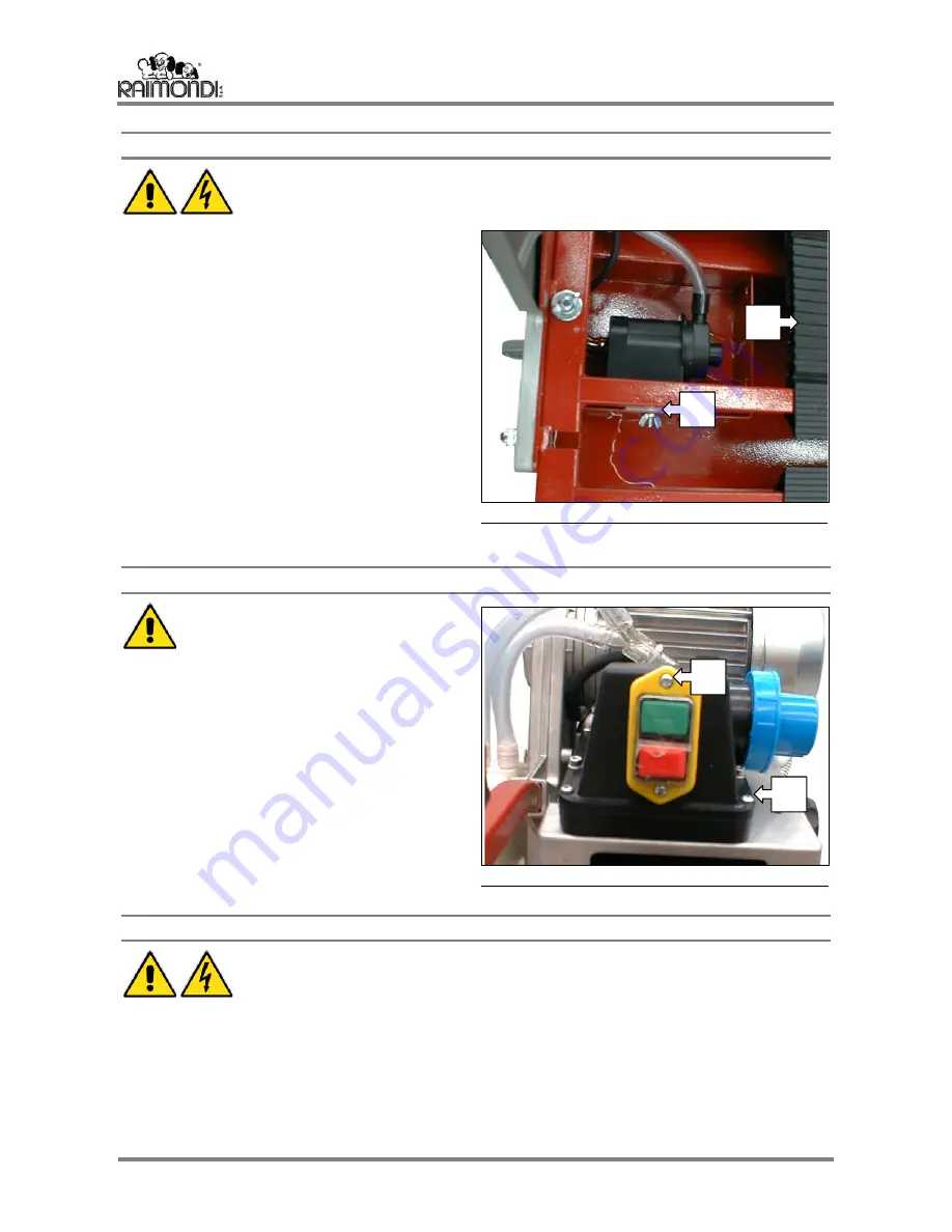
Remove the table (A). 


Empty the tank. 


Loosen the wing nut (B) and remove the pump. 


Open the terminal block cover of the main electric 
motor. 


Unplug the pump power supply cable. 


Pull the cable out of its sheath. 


Disconnect the water drainage hose. 


Replace the damaged pump with a new one, fit 
the cable into its sheath and restore connections. 


Close the terminal box cover being careful not to 
pinch the cables and correctly position the 
rubber gasket.


Reconnect the pump water drainage hose to the 
pump.  


Fasten the pump (A) in place by tightening the 
wing nut (B). 


Replacing the starter 


BEFORE PERFORMING ANY OPERA-
TION, MAKE SURE THAT THE MA-
CHINE IS UNPLUGGED. 


Open the terminal block cover of the main electric 
motor. 


Disconnect the wire coming from the starter. 


Loosen the screws that secure the starter (A) to 
the machine and replace the starter. 


Tighten the screws which were previously 
loosened. 


Resume the connections to the motor. 


Close the terminal block cover, being careful not 
to pinch the cables and correctly position the 
rubber gasket. 


Replacing the switch and/or thermal switch 


BEFORE PERFORMING ANY OPERATION, MAKE SURE THAT THE MACHINE IS 
UNPLUGGED.


Loosen the two screws (B). 


Remove the switch. 


Disconnect the cables. 


Replace the switch or thermal switch. 


Reconnect the cables. 


Tighten with the appropriate screws. 


F

IG

.


15 


F

IG

.


16 


A

A

Summary of Contents for PIKUS 105

Page 1: ...GB...

Page 2: ......

Page 3: ...ta 4 Technical data for motors 4 The machine units 5 Workstation 5 Safety devices 5 Noise 6 Safety Precautions 6 Transport of the package 6 Manual handling 6 Electrical Power Supply 7 Checks before us...

Page 4: ...URAL STONE Limitations The PIKUS 105 105DL 75 75DL saws are designed to be used only with the disks described above and must be water cooled Never use the machine with disks for wood working machines...

Page 5: ...correct working position While the machine is running never reach into the cutting zone C which is the gap between the two half plates During operation the operator must be standing on the front side...

Page 6: ...dB A To reduce the risk stemming from exposure use appropriate ear protection Also see Italian Law 277 91 for more specific indications Always wear goggles and protective gloves If the machine cuts ou...

Page 7: ...ed in the table TRANSFORMER 230V 50Hz 1 1kW 230V 60Hz 1 1kW 115V 50Hz 1 kW 115V 60Hz 1 kW DIFFERENTIAL 8 5A Id 20mA 8 5A Id 20mA 17A Id 20mA 17A Id 20mA ATTENTION ALWAYS REMEMBER TO PERIODICALLY CHECK...

Page 8: ...th BEFORE PERFORMING ANY OPERATION MAKE SURE THAT THE MACHINE IS UNPLUGGED The PIKUS machine can be used as follows With the motor assembly locked in place at the desired cutting depth tightening the...

Page 9: ...UTS Loosen the knob C and position the square at 45 Loosen the lever D and position the indicator G on the triangle E namely on the DIAGONAL tile measurement Tighten levers C and D Keeping the diamond...

Page 10: ...ait until the cooling water reaches the diamond disk Proceed with cutting slowly bringing the diamond disk up against the material to be cut Continue cutting keeping the forward speed steady Towards t...

Page 11: ...OND DISK DOES NOT TOUCH ANY PARTS OF THE MACHINE OR THE MA TERIAL TO BE ROUNDED OFF Position the tile to be rounded off with the glazed side facing upwards on the work surface and make certain that it...

Page 12: ...REGULARLY GREASE THE CHUCK BEARINGS IN THE POINT OF CONTACT WITH THE DISK HOLDER FLANGE CLEANING THE TANK Remove the two half plates Empty the water from the tank by removing the plug A at the bottom...

Page 13: ...nd on the disk guard To ensure that the disk is firmly secured in place tap on the shaft of the 22 mm Allen wrench with a hammer Refit the disk guard Manually rotate the disk to check that it has been...

Page 14: ...o the pump Fasten the pump A in place by tightening the wing nut B Replacing the starter BEFORE PERFORMING ANY OPERA TION MAKE SURE THAT THE MA CHINE IS UNPLUGGED Open the terminal block cover of the...

Page 15: ...HINE OR PARTS ARE TO BE DEMOLISHED FOLLOW THE INDICATIONS OUTLINED IN THE CURRENT LEGISLATION SWITCH HOLDER ABS ABS MACHINE BODY STEEL AC ALUMINIUM AL POLYAMIDE PA DISK GUARD SLIDE BAR COLUMN SQUARES...

Page 16: ...PIKUS 105 105DL PIKUS 75 75DL ENGLISH 16...

Page 17: ...423AS RON LOCKING PIN 18 263FE07D MOBILE DISK GUARD 19 114RE09D 114RE10D GUIDE PIKUS 75 GUIDE PIKUS 105 20 156NL09D 156NL10D AL GRID PIKUS 75 AL GRID PIKUS 105 21 158GB02D RING NUT 75 POS CODE PART N...

Page 18: ...SINGLE PHASE 230V 50Hz 1 1kW 8 5A 2800 min 1 MOTOR CLASS F D SINGLE PHASE 230V 60Hz 1 1kW 8 5A 3360 min 1 MOTOR CLASS F D SINGLE PHASE 115V 50Hz 1kW 17A 2800 min 1 MOTOR CLASS F D SINGLE PHASE 115V 60...

Page 19: ......
Page 20: ...PIKUS PIKUS Date of manufacture Serial n RAIMONDI S p A MODENA 2003 developed by TECNO DINAMICA S n c...

Reviews: