background image

43

ESP-LXD Controller

b

l

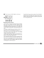
The Holding current is typically 10 mA or less. A reading of 50 mA or 

greater typically indicates a shorted decoder output.

Ping Sensor Decoder

b

g

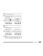
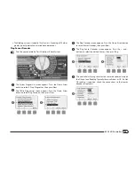
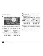
Turn the controller dial to Test All stations/Check System.

The  System  Diagnostics  screen  appears.  Press  the  Down  Arrow 

button to select 2-Wire Diagnostics; then press Next.

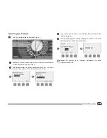
The  2-Wire  Diagnostics  screen  appears.  Press  the  Down  Arrow 

button to select Ping Decoders; then press Next.

1

2

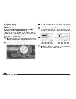
The Ping Decoder screen appears. Press the Down Arrow button 

to select Sensor Decoder; then press Next.

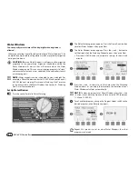
The  Ping  Sensor  Decoder  screen  appears.  Press  the  +  and  – 

buttons to select the desired Sensor; then press Ping.

3

4

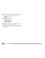
The controller will ping the selected sensor decoder and report 

the D-Level and Reading. Typically these will show as OK. If a Not 

OK  reading  is  reported,  check  the  connections  to  that  sensor 

decoder or replace it.

5

Summary of Contents for ESP-LXD

Page 1: ...ESP LXD Controller Installation Programming Operation Guide...

Page 2: ...e FCC Rules These limits are designed to provide reasonable protection against harmful interference in a residential installation Thisequipmentgenerates uses andcanradiateradiofrequencyenergy and if n...

Page 3: ...p Programs 9 Set Up Programs Optional 9 Review Setup 9 Optional Setup 9 AUTO 10 Automatic Operation 10 Alarm Conditions 11 Decoder Address Alarms 11 FloWatchTM Alarms 11 Review Alarm Messages 11 Reset...

Page 4: ...ationsTM 58 Set SimulStationsTM for Program 58 Set SimulStationsTM for Controller 59 Station Sequencing 60 Section E Options Special Features 61 Backup and Recall Programs 61 Store Default Programs 61...

Page 5: ...f 2 Wire Path 110 Close Master Valves 112 Section H Installation 113 Install the Controller 113 Installation Checklist 113 Check Box Contents 113 Select Location for Controller 114 Gather Installation...

Page 6: ...this page intentionally left blank...

Page 7: ...ules can easily be expanded to address up to 200 total stations Controller Features The ESP LXD controller has a variety of advanced features to help you manage water efficiently including l l Flow po...

Page 8: ...arious types of alarm conditions See Alarm Conditions for more details on how to review and clear alarms Controls Switches and Indicators Key operational features of the ESP LXD Controller front panel...

Page 9: ...th designs are supported Star Pattern A Star Pattern allows branching as often as necessary without ever looping the wire back to the controller This generally allows more design flexibility but at th...

Page 10: ...Lengths for 2 Wire Paths Nominal Wire Size Ohms per 1000 or Ohms per Km per conductor Max Length For Critical Path Star Loop Km Miles Km Miles 2 5 mm2 7 5 Ohms Km 3 00 1 86 12 00 7 46 14 AWG 2 58 Ohm...

Page 11: ...e weather sensor decoders Local Sensor The ESP LXD controller can also interface to a local sensor such as a rain shutoff device The local weather sensor connects directly to the ESP LXD M50 module vi...

Page 12: ...Stations Valves or stations operate at times as specified by irrigation programs The controller sends signals to the appropriate decoder powering the valve solenoid to open or close When additional s...

Page 13: ...of day that irrigation begins this is the time that the first station in the program begins watering all other stations in the program then follow in sequence b b NOTE The term start time refers to t...

Page 14: ...afe location when you re finished working with it We recommend hanging it on the hook inside the controller cabinet door as shown below Remote Programming The ESP LXD controller can be programmed whil...

Page 15: ...ge 20 1 1Set up flow sensors optional Page 22 Set Up Programs A B C D 4 4Select program A B C or D Page 14 4 4Set watering start times Page 25 4 4Select watering days Page 26 4 4Set station run time s...

Page 16: ...is canceled g g Turn the controller dial to AUTO A The Auto screen is displayed with the current day and time shown B WhenaprogramisrunninginAUTOmode thestationnumberwill display on the screen Press...

Page 17: ...larms ThecontrollerwillalarmforcertainflowconditionsifyouhaveFloWatch set up See Section F Flow Management for more details Review Alarm Messages A When an alarm condition is detected the alarm light...

Page 18: ...front panel B Locate the RESET button on the back of the front panel 1 2 C Use a pen or pencil to depress the RESET button D The Rain Bird screen appears confirming reset 3 4 Optional Features Station...

Page 19: ...current hour then press Next b b NOTE Be sure to set the hour correctly to either AM or PM l l Press and HOLD buttons to accelerate settings for hours and minutes B Press the and buttons to set the cu...

Page 20: ...programming the controller any program specific information you enter such as start times or watering days will affect only the selected program Setup Wizards Setup Wizards take you through each step...

Page 21: ...in Bird valves which the ESP LXD supports Select your valve type if present then press Next 3 4 b b NOTE Rain Bird residential valves DV and JTV series are not compatible with ESP LXD decoders Use Rai...

Page 22: ...p valve types before setting up master valves g g Turn the controller dial to Setup Wizards A The Setup Wizards screen appears Press the Down Arrow button to select Master Valves then press Next B The...

Page 23: ...o assign MVs to FloZones press Next to continue 5 6 G On the FloZone assignment screen press the and buttons to associate the MV with the appropriate FloZone then press Next b b NOTE A FloZone can use...

Page 24: ...ther Sensors g g Turn the controller dial to Setup Wizards A The Setup Wizards screen appears Press the Down Arrow button to select Weather Sensors then press Next B The Weather Sensor Setup screen ap...

Page 25: ...eather Sensor Installation for more details Custom Pause Sensors When a weather condition becomes true a Custom Pause sensor will stop irrigation and also stop the irrigation timer When the condition...

Page 26: ...ions follow the previous instructions to set up valve types master valves and weather sensors if present g g Turn the controller dial to Setup Wizards A The Setup Wizards screen appears Press the Down...

Page 27: ...en lets you assign stations to FloZones if you re using either the FloWatch or FloManager features Press the and buttons to see available FloZones or if you re not using FloZones select zero then pres...

Page 28: ...press Next B The Flow Sensor Setup screen appears Press the and buttons to enter the desired flow sensor number then press Next 1 2 C Press the and buttons to enter the decoder address pressing Next...

Page 29: ...g Next and Back to navigate between the number setting fields then press Next b b NOTE An alarm will show if a duplicate sensor decoder address is entered for more than one flow sensor See Section A A...

Page 30: ...ter the MV you wish to assign to the flow sensor Each assigned FloZone will be shown below the MV field 7 e e Repeat this process to set up additional custom flow sensors Be sure to note each flow sen...

Page 31: ...ars Press the and buttons to set Start Time for the current program then press Next l l Press and HOLD buttons to accelerate settings for hours and minutes b b NOTE If the desired program is not selec...

Page 32: ...he controller dial will carry over to the Watering Cycles day settings and vice versa g g Turn the controller dial to Mon 1 A The Custom screen appears Press the Allow or Prevent buttons to choose whe...

Page 33: ...he desired program is not selected use the Program Select switch to change it See Section B Program Select Switch for more details B Press the and buttons to set the Station Run Time Range can be from...

Page 34: ...28 ESP LXD Controller this page intentionally left blank...

Page 35: ...een appears with Confirm Programs selected press Next B The Confirm Programs screen appears with Program Summary selected press Next 1 2 C The Program Summary screen appears providing a summary of Run...

Page 36: ...t Times review screen appears with start times displayed for the currently selected program Press Next b b NOTE If the desired program is not selected use the Program Select switch to change it See Se...

Page 37: ...emaining until next watering date displayed Press Next J The Calendar Day Off review screen appears with all selected calendar days off displayed Press Next i j K The Station Delay review screen appea...

Page 38: ...he maximum number of stations that can operate simultaneously for that program are displayed Press Next o p Q The Maximum Number of SimulStations for controller review screen appears with the maximum...

Page 39: ...n appears and total RunTime is displayed for the currently selected program b b NOTE If the desired program is not selected use the Program Select switch to change it See Section B Program Select Swit...

Page 40: ...row button to select Station Run Time then press Next 1 2 C The Sta Run Time Per Day screen appears with total Run Time displayed for the currently selected station in all four programs For programs w...

Page 41: ...the controller dial to Test All stations Check System A The System Diagnostics screen appears Press the Down Arrow button to select Test All stations then press Next B The Test All stations screen ap...

Page 42: ...are running higher priority stations will irrigate prior to medium priority stations and medium priority stations will irrigate prior to lower priority stations See Section B Station Setup and Confirm...

Page 43: ...oceed with Short Finding 3 4 E A confirmation screen appears stating that irrigation has been disabled F A second confirmation screen appears showing that Short Finding is now On and in progress 5 6 b...

Page 44: ...ton to select station Decoder Test then press Next 1 2 C A confirmation screen appears press Start D A second confirmation screen appears to confirm the Decoder Test is In Progress 3 4 E The DecoderTe...

Page 45: ...39 ESP LXD Controller this page intentionally left blank...

Page 46: ...decoders X 1 0 mA Quantity of active decoders X 17 5 mA Quantity of other SD210 decoders X 8 0 mA Approximate total system amperage in mA Single address station decoders include the FD 101 FD 102 dec...

Page 47: ...roximately equal to the amperage calculations detailed above for both A and B Three flags also appear below the voltage and amperage readings For a normal healthy system the flags should typically rea...

Page 48: ...n Arrow button to select Ping Decoders then press Next 1 2 C The Ping Decoder screen appears with Station Decoder selected Press Next to ping a Station decoder or else press the Down Arrow button to s...

Page 49: ...B The 2 Wire Diagnostics screen appears Press the Down Arrow button to select Ping Decoders then press Next 1 2 C The Ping Decoder screen appears Press the Down Arrow button to select Sensor Decoder...

Page 50: ...current weather conditions b Inactive installation has not been completed or the sensor is not linked to any stations c PAUSING current weather condition has caused the sensor to pause irrigation d PR...

Page 51: ...controller dial to Test All stations Check System A The System Diagnostics screen appears Press the Down Arrow button to select Wthr Sensor Status then press Next B The MV Status screen appears showin...

Page 52: ...46 ESP LXD Controller this page intentionally left blank...

Page 53: ...ment setting d d CAUTION Setting a small number for the Seasonal Adjustment percentage will greatly reduce watering and setting to 0 will cancel irrigation entirely Use caution when making Seasonal Ad...

Page 54: ...lect the month you would like to adjust then press Next D Press the and buttons to set the Seasonal Adjustment percentage from 0 300 l l Press and HOLD buttons to accelerate settings for percentages 3...

Page 55: ...Next B The Seasonal Adjust by Month screen appears Press the Down Arrow button to select Select PGMs then press Next 1 2 C Press the Yes or No buttons to set Monthly Adjust for the current selected pr...

Page 56: ...f you have a rain sensor attached to your controller it may be unnecessary to manually program a Rain Delay Consult the rain sensor device documentation for more details g g Turn the controller dial t...

Page 57: ...ntroller dial to Delay Watering A The Delay Watering screen appears Press the Down Arrow button to select Calendar Day Off then press Next B The Calendar Day off screen appears showing up to 5 schedul...

Page 58: ...Watering Start Times are set to occur within the Water Window See Section A Watering Start Times for more details Set Up Water Window g g Turn the controller dial to Delay Watering A The DelayWatering...

Page 59: ...dless of the Watering Cycle irrigation will start only on days of the week where program starts are allowed See Section B Select Days to Water for more details It s important to select allowed irrigat...

Page 60: ...repeat the selection process as desired 3 e e Change the Program Select switch and repeat this process to set Watering Cycles for other programs as desired b b NOTE Watering day selections carry over...

Page 61: ...2 C Press the and buttons to set the first date for the Watering Cycle to begin then press Next l l Press and HOLD buttons to accelerate settings for dates D The Watering Day Cycle screen appears Pres...

Page 62: ...s A The Station Settings screen appears with Cycle Soak selected press Next B The Cycle Soak screen appears Press the and buttons to enter the desired station number then press Next 1 2 C Press the an...

Page 63: ...etails g g Turn the controller dial to Station Settings A The Station Settings screen appears Press the Down Arrow button to select Station Delay then press Next B The Delay Between stations screen ap...

Page 64: ...al we recommend enabling FloManager and setting program level and LXD level SimulStations to a fairly high number This will allow FloManager to provide maximum irrigation based on your system s hydrau...

Page 65: ...ess Next 1 2 C The ESP LXD Maximum Number of SimulStations screen appears Pressthe and buttonstosetthemaximumnumberofirrigation stations from 1 to 8 that can operate simultaneously then press Next D P...

Page 66: ...ation High Medium Low 2 Station run time Longest run time shortest run time 3 Station number 1 2 3 4 Program assignment A B C D b b NOTE If FloManager is turned ON then the default Station Sequencing...

Page 67: ...urns the controller programming to the normal irrigation schedule d d CAUTION The Backup Programs feature saves and restores ALL irrigation programming in ALL programs A B C D b b NOTE The ESP LXD als...

Page 68: ...n press Next B The Backup Programs screen appears Press the Down Arrow button to select Recall Programs then press Next 1 2 C A confirmation screen appears To Recall Programs press and hold down the Y...

Page 69: ...A The Special Features screen appears Press the Down Arrow button to select Backup Programs then press Next B The Backup Programs screen appears Press the Down Arrow button to select Delayed Recall t...

Page 70: ...es solid when optional barcode scanning pen is connected 1 2 3 Programming Backup Cartridge PBC LXD Barcode Scanning Feature With a PBC LXD cartridge installed you can also set up Field Decoder addres...

Page 71: ...d at the top left corner inside the cartridge bay of the controller front panel 3 D Orient the cartridge so that the two bottom hinges fit into the hinge openings at the bottom of the cartridge bay Th...

Page 72: ...s that are assigned automatically Backup01 through Backup08 The names cannot be changed but the date and time stamp update automatically whenever a particular file is used Unused files display as Unus...

Page 73: ...Q PBC Settings A The PBC Main Menu appears Press the Down Arrow button to select Restore Programs then press Next B The PBC Restore screen appears Press the or buttons to choose a Restore file then pr...

Page 74: ...ately Rain Bird recommends using a Unitech MS100 2 barcode pen with 9 pin female serial connector Go to www ute com for more details Install Barcode Scanning Pen For this installation you will need th...

Page 75: ...o that the two bottom hinges fit into the hinge openings at the bottom of the cartridge bay Then gently swing the PBC LXD up into place snapping the top latch 5 F Route the PBC LXD RJ45 Connector Cabl...

Page 76: ...ing Guide that came with the ESP LXD controller 1 B On page 26 of the Programming Guide under Barcode Scanning Pen Setup locate Setup Barcode 1 Scan the barcode lengthwise as shown You ll hear audible...

Page 77: ...arcode Pen screen appears with instructions 2 3 D Scan any station Number Barcode as shown on pages 6 25 of the Programming Guide You ll hear an audible beep to confirm when the scan was successful E...

Page 78: ...s will not update or replace your decoder addresses A Locate the Programming Guide that came with the ESP LXD controller 1 B Ensure that the station Decoder Address Labels are affixed in the proper lo...

Page 79: ...on 1 if necessary G To scan master valve flow sensor or weather sensor decoders from the Scan When Ready screen press the Type button to select the desired device Then repeat the scanning process as p...

Page 80: ...he top item on the Special Features main menu B The Set Language screen appears Press the and buttons to select the desired language 1 2 Set Hours Mode You can set the ESP LXD controller to display ti...

Page 81: ...own Arrow button to select NOMV Cycling then press Next B A confirmation screen appears press Next when ready 1 2 C The NOMV Cycling screen appears Press the and buttons to set the desired time for cy...

Page 82: ...76 ESP LXD Controller this page intentionally left blank...
Page 83: ...r of MVs It s important to fully understand your system s hydraulic properties to set up your water sources MVs and FloZones appropriately For more information on setting up MVs and FloZones See Secti...

Page 84: ...ipe Size will default to Inches on 60 Hz and to millimeters on 50 Hz FloManagerTM One of the most powerful flow management features in the ESP LXD controller is FloManager which enables the controller...

Page 85: ...e flow sensing hardware installed you may be able to estimate flow rates based on the irrigation hardware installed on a particular station or FloZone and manually enter this rate Enable Or Disable Fl...

Page 86: ...Module selected press Next B The Flow Smart Module PGM screen appears with Set Flow Rates selected press Next 1 2 C The Set Flow Rates screen appears Press the Down Arrow button to select Set Station...

Page 87: ...e Press buttons 2 and 4 to navigate between the FloZone and Flow Rate fields l l Press and HOLD buttons to accelerate settings for GPM b b NOTE MaximumFloZoneflowratesareusedonlybyFloManager FloWatch...

Page 88: ...ler lets you set the flow rates you expect or to automatically Learn Flow rates based on real usage Once flow is learned or manually entered the SEEF and SELF settings let you define the parameters fo...

Page 89: ...Arrow to select FloWatch then press Next 1 2 C The FloWatch screen appears Use the Down Arrow to select FloWatch On Off then press Next D Press the On button to enable FloWatch or else press Off to di...

Page 90: ...selected press Next B The Flow Smart Module PGM screen appears Use the Down Arrow to select FloWatch then press Next a b C The FloWatch screen appears with SEEF SELF Settings selected press Next D Th...

Page 91: ...the master valve s on the FloZone when a high flow condition is detected The controller will not attempt to diagnose if the problem is on the mainline or downstream of a valve C Alarm Only allows the...

Page 92: ...ly allows the controller to issue an alarm condition but take no other action Press the and buttons to set the SELF Action then press Next J The Delay to Re Enable screen appears allowing you to selec...

Page 93: ...t 1 2 C The Set Flow Rates screen appears with Learn Flow selected press Next D The Learn Flow screen appears with All stations selected press Next 3 4 b b NOTE Ensure you have runtimes set up for all...

Page 94: ...b NOTE Be sure to Learn Flow again if you make any changes to your system which affect its hydraulics b b NOTE If the flow rates for one or more stations seem low check your flow metering hardware and...

Page 95: ...select the stations you would like to include Press Next and Back buttons to select stations then press Next F Press the and buttons to set the timed delay when you want the Learn Flow exercise to st...

Page 96: ...low Alarms g g Turn the controller dial to Module Status A The Smart Module Status screen appears with Flow Smart Module selected press Next B The Flow Module Status screen appears with View Flow Alar...

Page 97: ...screen appears with View Flow Alarms selected press Next 1 2 C The Review Clear Alarms screen appears Press the Down Arrow button to select FloZone Flow Alarms then press Next D The FloZone Flow Alar...

Page 98: ...th Flow Smart Module selected press Next B The Flow Module Status screen appears with View Flow Alarms selected press Next 1 2 C The Review Clear Alarms screen appears Press the and button to select C...

Page 99: ...xt B The Flow Module Status screen appears Press the Down Arrow button to select View Flow Rates then press Next 1 2 C The Flow Rates screen appears with View station Rates selected press Next D The s...

Page 100: ...rs Press the Down Arrow button to select View Flow Rates then press Next 1 2 C The Flow Rates screen appears Press the Down Arrow button to select View FloZone Rates then press Next D The FloZone Flow...

Page 101: ...press Next B The Flow Module Status screen appears Press the Down Arrow button to select View flow Logs then press Next 1 2 C The Flow Logs screen appears showing month to date and last month water c...

Page 102: ...The Flow Module Status screen appears Press the Down Arrow button to select View Current flow then press Next 1 2 C The View Current Flow screen appears Press the and buttons to select the desired Fl...

Page 103: ...ler dial to Module Programming A The Smart Module PGM screen appears with Flow Smart Module selected press Next B The Flow Smart Module PGM screen appears with Set Flow Rates selected press Next 1 2 C...

Page 104: ...98 ESP LXD Controller this page intentionally left blank...

Page 105: ...he controller does not recognize an installed module carefully remove it and review the installation instructions in Section H of this manual Then re install the module and repeat this process Section...

Page 106: ...r the cleared Programs If no Programming exists then an Alarm will be displayed See Section A Alarm Conditions for more details Clear Individual Program g g Turn the controller dial to Clear Programs...

Page 107: ...ograms A The Clear Programs screen appears Press the Down Arrow button to select All Programs then press Next B A confirmation screen appears To Clear All Programs press and hold down the Yes button f...

Page 108: ...t B A confirmation screen appears To Restore Factory Defaults press and hold down the Yes button for four seconds If you re not sure press No 1 2 C A confirmation screen appears 3 d d CAUTION Be very...

Page 109: ...reen appears Press the and buttons to enter the station you want to run manually then press Next l l Press and HOLD buttons to accelerate settings for hours and minutes 1 2 C The Station Run Time will...

Page 110: ...the desired Program is not selected use the Program Select switch to change it See Program Selection in Section A for more details 1 2 C A confirmation screen appears 3 e e Repeat this process to man...

Page 111: ...er dial to Manual Watering A The Manual Watering screen appears Press the Down Arrow button to select MV Water Window then press Next B The MV Water Window screen appears with MV Water Window selected...

Page 112: ...ater Window screen appears allowing you to choose which MVs to include in the MV Water Window Press theYes button to include the selected MV in the Water Window or press No to exclude it H Press the N...

Page 113: ...ng screen appears Press the Down Arrow button to select MV Water Window then press Next B The MV Water Window screen appears Press the Down Arrow button to select Manual MV Open then press Next 1 2 C...

Page 114: ...n g g Turn the controller dial to Manual Watering A The Manual Watering screen appears Press the Down Arrow button to select Test All stations then press Next B The Test All stations screen appears Pr...

Page 115: ...109 ESP LXD Controller this page intentionally left blank...

Page 116: ...you may want to turn off the 2 Wire path such as when you re maintaining your system The ESP LXD controller lets you do this automatically so you do not need to un wire the 2 Wire path from the conne...

Page 117: ...ss No D A confirmation screen appears 3 4 E The OFF dial position screen will now display the message 2 Wire Path Off 5 e e Repeat this process and press the On button to restore power to the 2 Wire p...

Page 118: ...osed Master Valves remain closed g g Turn the controller dial to OFF A The All Watering Off screen appears Press the MV Close button B A confirmation screen appears To close all master valves press an...

Page 119: ...you complete the following steps in order For your convenience a check off box is provided for each step 1 1Check box contents Page 113 1 1Select a location Page 114 1 1Gather installation tools Page...

Page 120: ...s safe from potential vandalism l l Is outside the range of operating sprinklers Gather Installation Tools Before beginning installation gather the following tools and materials 1 1Slotted Head Screwd...

Page 121: ...towards you to open the door swinging it to the left D To open the controller front panel grasp the crescent shaped handle on the right hand side of the front panel 4 3 E Pull it towards you to open...

Page 122: ...or other solid surface B Use a tapping tool or nail and hammer to tap pilot holes through the five mounting hole marks and into the mounting surface Then remove the template and drill holes in the mo...

Page 123: ...ors unless you plan to upgrade your controller with an optional ET Manager cartridge If you plan to add the ET Manager then we recommend installing the module into the bottom set of connectors to allo...

Page 124: ...B Carefully fasten the module onto the controller backplane pressing firmly until it snaps into place 2 b b NOTE To remove the module again press in on the two release buttons on either side of the mo...

Page 125: ...2 3 D Using a thin blade screwdriver connect the two wire ends to a set of large two wire path terminals on the ESP LXD decoder module When finished tug gently on the wires to make sure the connection...

Page 126: ...the decoders connected to the controller You will need to connect power supply wires to the transformer s three wires c c WARNING Electric shock can cause severe injury or death Make sure power suppl...

Page 127: ...alled D Feed the three supply wires from the power source through the conduit into the wiring compartment 3 4 2 3X 3 wires E Using wire nuts connect the wires accordingly 53X c c WARNING The ground wi...

Page 128: ...erate under battery power for remote programming This feature is especially useful if the controller is installed in an area that is not easily accessible It also lets you enter program information be...

Page 129: ...or this task The stripping should be done by carefully scoring the outer jacket in at least two places and then gently flexing the cable to loosen the portion of the outer jacket to be removed It may...

Page 130: ...e color combination and decoder address combinations on the side of the decoder Be sure to connect the wires to the different valves in the order you want your valves controlled and be sure to affix t...

Page 131: ...SP 1s required and where they will need to be installed B At the first LSP 1 location install a grounding device typically a grounding rod or plate which meets all local codes near the 2 Wire path C S...

Page 132: ...e to all local codes C Follow the field decoder installation process to splice the two blue wires from the flow sensor to the red and black wires in the two wire path completing the splice with approv...

Page 133: ...the ESP LXD decoder module When finished tug gently on the wires to make sure the connections are tight 2 b b NOTE If your weather sensor requires 24V power from the controller the connectors to the l...

Page 134: ...128 ESP LXD Controller this page intentionally left blank...

Page 135: ...d valve types b b NOTE To find a switch code that works with your valve you may need to use the trial and error method Example Arrows in chart show Activation Time 40 ms milliseconds Holding Voltage 2...

Page 136: ...de the controller sends a signal telling the decoder when to activate the master valve or pump The switch code can vary depending on how your system was installed Below we will cover some of the more...

Page 137: ...EN61000 4 8 EN61000 4 11 Manufacturer s Name Rain Bird Corporation Manufacturer s Address 9491 Ridgehaven Court San Diego CA 92123 619 671 4048 Equipment Description Irrigation Controller Equipment Cl...

Page 138: ...hpoint Road Tucson AZ 85756 2012 Rain Bird Corporation Rain Bird SimulStations FloManager FloWatch FloZone and Cycle Soak are registered trademarks of Rain Bird Corporation All rights reserved www rai...

Reviews: