


Weather Station - Model “PRO”
Nov., 2001 Page
24
Model “PRO”- Weather Station
Cozz GT27145B
GENERAL:
The Model PRO weather station comes
with the some of the sensing
instruments, and sensor wiring to
datalogger completely assembled as a
unit on a cross-arm. The Solar
Radiation Pyranometer - along with the
leveling device are mounted on a
bracket, which in turn is mounted on the
cross-arm of the Enclosure. On this
end of the cross-arm the “Tipping Rain
Bucket” is also mounted at the factory.
On the opposite end of the cross-arm is
attached the mounting bracket, which
has been factory installed, for the Wind
speed and Wind direction sensing
instruments. The Temperature and
Relative Humidity sensors are on the end
of their cable and only need installing
into the radiation shield. The cables for
each of these sensors are mounted in the
cross-arm and terminated at the proper
location of each sensor. The cables only
need to be routed and plugged into the
proper connectors on the back of the
back panel of the ET Enclosure.
SUPPLIED COMPONENTS
(1)
Sensor Cross-Arm
(1)
Met One 034A Wind Sensor
(1)
034A Mounting Shaft
(1)
Radiation Shield
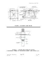
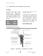
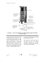
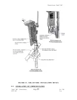
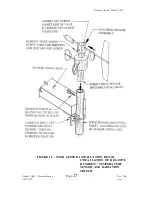
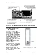
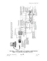
INSTALLATION OF CROSS-ARM
TO ET ENCLOSURE:
Refer to FIGURE 11 below:
Remove the four (4) Phillips head
screws from the bottom center of the
cross-arm. With the Enclosure cover
removed, place the cross-arm on top of
the Enclosure. The cross-arm needs to
be oriented along a due east to due west
axis. If necessary adjust the Enclosure
on the tower to properly orient the cross-
arm. Also be sure that the opening in
the middle and one side of the cross-arm,
where the sensor cables exit, is to the
back of the Enclosure so that the cables
can enter the top of the cover that fits
over the cable connectors on the back of
the Enclosure. Line up the four
threaded holes on the under side of the
cross-arm (where you just removed the
screws) with the four holes in the top of
the Enclosure. Attach the cross-arm to
the Enclosure by inserting the four (4)
screws, from in side the enclosure up
through the top and into the threaded
holes of the cross-arm. Tighten the
screws securely.
REFER TO NEXT PAGE FOR FIGURE 11