


Weather Station - Model “PRO”
Model “PRO” - Weather Station
Page
37
Nov., 2001
GT27145B Cozz
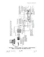
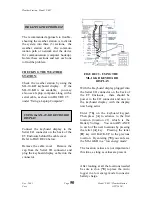
10.0 INSTALLATION AT CENTRAL COMPUTER
MODEL PRO - SH ~ Direct
Connected:
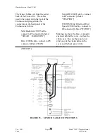
Refer to FIGURE 22 below:
SUPPLIED COMPONENTS
(1) SMR-5A RAD Modem
(1) 5 Foot 4-Wire Patch Cord
(1) 25 Foot #10 AWG Ground
Wire
(1) Surge Protection Box
INSTALLATION
Attach the 5 foot 4-wire patch cord to
the SRM-5A RAD modem unit, which
is furnished as part of the weather
station. Connect the GREEN (XMT+)
wire to the “XMT+” terminal of the
RAD modem. Connect the WHITE
(XMT-) wire to the “XMT-“ terminal,
the RED (RCV+) wire to the “RCV+”
terminal and the BLACK (RCV-) wire to
the “RCV-“ terminal.
Connect the SRM-5A RAD modem
directly to the serial port of the computer
or use a 9-pin to 25-pin adapter if
required.
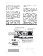
Mount the Surge Arrestor Box, which is
furnished as part of the weather station,
in a suitable location near the computer
(within less than 5 feet, as the patch
cord is only 5 feet long).
Take the other end of the Patch Cord,
that you have previously connected to
the modem, and connect the GREEN
(XMT+) wire to the upper left connector
in the Surge Arrestor Box. Connect the
WHITE (XMT-) wire to the upper right
connector, connect the RED (RCV+)
wire to the lower right connector and the
BLACK (RCV-) wire to the lower left
connector of the surge arrestor box.
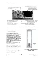
Just outside the building of the central
computer location, install an 18” x 24”
rectangular valve box with cover over
one ground rod of a 3-rod grounding
grid. (You may use the 3-rod grounding
grid for the central Interface unit, etc. if
located nearby).
Furnish and install and MGP-1
grounding plate assembly on the ground
rod in the valve box. Furnish and install
in the MGP-1 grounding plate assembly
two (2) MSP-1 Pipe Surge Arrestors.
Be sure to have the end marked
“EQUIP” toward the central equipment
and the “LINE” end toward the weather
station. Ground both ends of each of
the MSP-1 Surge Arrestors to a screw on
the
MGP-1 grounding plate assembly.
Using a piece of Belden #9883 direct
burial cable (of sufficient length to reach
from the Surge Arrestor Box to the
Valve box) take the Green and Black
twisted pair of wires and connect the
GREEN (XMT+) wire to the upper left
terminal in the Surge Arrestor Box.
Connect the BLACK (XMT-) wire to the
upper right terminal in the Surge
Arrestor Box. Take the Red and Black
twisted pair of wires and connect the
RED (RCV+) wire to the lower right
terminal of the Surge Arrestor Box.
Connect the BLACK (RCV-) wire to the