


Weather Station - Model “PRO”
Nov., 2001 Page
38
Model “PRO”- Weather Station
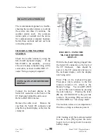
Cozz GT27145B
lower left terminal of the Surge Arrestor
Box. Leave the third pair of twisted
wires, consisting of a Black and White
wire disconnected and for a spare pair.
The copper drain wire shall also be left
disconnected.
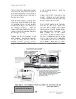
Route the Belden cable, out of the
building, under ground and out to the
valve box. Taking the Green and Black
twisted pair of wires, connect the
GREEN (XMT+) wire to the RED wire,
on the end marked “EQUIP”, to one of
the MSP-1 Pipe Surge Arrestor that you
have installed in the MGP-1 Grounding
Plate Assembly. The BLACK (XMT-)
wire shall be connected to the BLACK
wire, on the end marked “EQUIP”, of
this MSP-1 Surge Arrestor.
Next take the Red and Black twisted pair
of wires of the Belden cable and connect
the RED (RCV+) wire to the RED wire,
on the end marked “EQUIP”, of the
second MSP-1 pipe surge arrestor.
Connect the BLACK (RCV-) wire to the
BLACK wire, on the end marked
“EQUIP”, of this second MSP-1 pipe
surge arrestor.
The third twisted pair, consisting of a
Black and White wire pair, shall be left
as a spare and un-connected. The
copper drain wire shall also be left
disconnected.
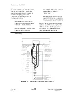
A Belden #9883 Cable, consisting of
three twisted pair of wires, a copper
drain wire and an aluminum shield with
an outer insulation for direct burial,
shall be run underground form the
central
location valve box out to the weather
station location. At the valve box, at
the central location, take the Green and
Black pair of wires and connect the
GREEN (XMT+) wire to the RED wire,
coming from the end marked “LINE”,
of the first MSP-1 pipe surge arrestor.
Connect the BLACK (XMT-) wire from
this pair, to the BLACK wire, coming
from the end marked “LINE”, of the
first MSP-1 pipe surge arrestor.
Take the Red and Black twisted pair of
wires, of the Belden cable and connect
the RED (RCV+) wire from this pair, to
the RED wire coming from the end
marked “LINE”, of the second MSP-1
pipe surge arrestor. Connect the
BLACK (RCV-) wire from this pair, to
the BLACK wire coming from the end
marked “LINE”, of the second MSP-1
pipe surge arrestor.
The third twisted pair, consisting of a
Black and White wire pair, shall be left
as a spare and un-connected. The
copper drain wire shall also be left
disconnected.
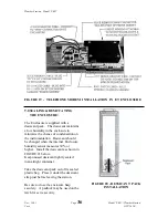
To the center ground terminal in the
Surge Arrestor Box - connect one end of
the #10 gauge bare copper ground wire.
Route this wire out the bottom of the
box, underground out to the valve box
and connect it to the ground rod using a
brass clamp. Keep this ground wire as
short and as straight as possible with NO
sharp bends or “kinks”.
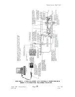
For connections and wiring at the
Weather Station, refer to Section 5.0 of
this manual.
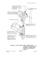
REFER TO NEXT PAGE FOR FIGURE 21