Installation Instructions continued from page 9
10.
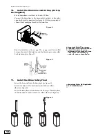
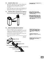
Install the Drain Line and Air Gap (Air Gap
Not Supplied)
• For all drain lines, use at least a 1/2 inch I.D. line.
• Connect the drain line to the drain outlet on back of the valve,
opposite the inlet connection (see figure 4). A fitting is required to
connect the female pipe thread to the drain line.
• Run the drain line to the air gap. The air gap must be installed
between the end of the drain line and the drain to prevent possible
back siphoning (see figure 5).
11.
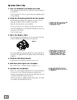
Install the Brine Safety Float
• Insert the brine well into the brine tank (see figure 6).
• Attach the brine well to the brine tank with the overflow
elbow (see figure 6).
• Insert the safety float into the brine well. The top of the safety float
should be about 5 inches from the overflow elbow (see figure 6).
10
Important Note: The air gap
should be two times the diam-
eter of the drain line or a
minimum of two inches. Please
check your local plumbing
codes to ensure compliance.
1/2" ELBOW
1/2" DRAIN LINE
1/2" SPRING CLIP
Figure 4
Figure 5
Figure 6
Important Note: Not Applicable
for TC-CAB Models.
Summary of Contents for TC 100 CV
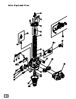
Page 18: ...18 18 Valve Exploded View ...
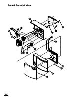
Page 20: ...20 Control Exploded View 20 ...
Page 23: ...23 Notes ...
Page 44: ...44 Vista despiezada de la válvula ...
Page 46: ...46 Vista despiezada del control ...
Page 49: ...49 Notas ...
Page 50: ...50 Notas ...
Page 51: ...51 Notas ...

