9
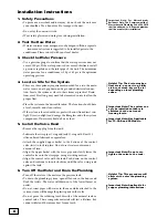
• Avoid short connections of pipe between the system and the
water heater. If you can’t avoid a short connection, move the
system to another location. As a last resort, install a heat trap or
check valve. If this causes “water hammer”, install a water
hammer suppressor.
7. Provide Untreated Water for Irrigation or
Outdoor Watering
• If available, run an untreated water line to ourside faucet or
provide a hose connection on untreated line prior to system.
8. Install the Pipe Connector (Yoke) to the
Bypass Valve
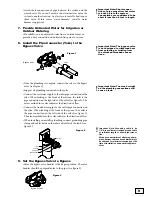
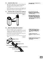
• Once the plumbing is complete, connect the yoke to the bypass
valve (see figure 1).
• Support all plumbing connected to the yoke.
• Connect the raw water supply to the inlet pipe connection of the
yoke. When looking at the front of the system, the inlet is the
pipe connection on the right side of the valve (see figure 2). The
arrow molded into valve indicates the direction of flow.
• Connect the treated water pipe to the outlet pipe connection on
the yoke. When looking at the front of the system, the outlet is
the pipe connection on the left side of the valve (see figure 2).
The arrow molded into the valve indicates the direction of flow.
• When installing on metallic plumbing, connect grounding pipe
clamp and cables between the inlet and outlet of the tank. (see
figure 2)
9. Set the Bypass Valve to Bypass
•Move the bypass valve handles to the bypass position. The valve
handles should be perpendicular to the pipes (see figure 3).
Important Note: Too much weight
on the plumbing connections will
cause a leak.
Important Note: Short connec-
tions of pipe may allow hot water
to back up into the system.
Connections are considered to be
short if less than 6 feet in length.
Important Note: The bypass valve
is not designed to withstand heat
from soldering or twisting from
the attached threaded connec-
tions.
Yoke
Bypass Valve
Figure 1
Bypass Position
Figure 3
!
Important Note: Grounding cable to be
1/4” bronze (bare) stranded ground cable
of sufficient length to allow pipe joint to
flex.
Ground conductivitity of all piping, equip-
ment, devices, cable and connections must
be checked for electrical continuity at the
time of installation and periodically there-
after.
GROUND
PIPE CLAMP
GROUND CABLE
OUTLET
YOKE
INLET
Figure 2
Summary of Contents for TC 100 CV
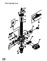
Page 18: ...18 18 Valve Exploded View ...
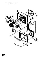
Page 20: ...20 Control Exploded View 20 ...
Page 23: ...23 Notes ...
Page 44: ...44 Vista despiezada de la válvula ...
Page 46: ...46 Vista despiezada del control ...
Page 49: ...49 Notas ...
Page 50: ...50 Notas ...
Page 51: ...51 Notas ...

