1
8
)
Installation:
Make sure that the voltage supply corresponds to the rated voltage. Remove the cover (faceplate)
from the electronic board and make the electrical connection according to the instructions shown
inside. This controller can also be used with a single-phase pump with electrical demand greater than
16A, or a three-phase pump, using an auxiliary remote control switch (115V coil). In this case the
electrical connections must be made as shown in the diagram, Fig. 3.
1
8
.2 Electrical Connection (Fig. 2)
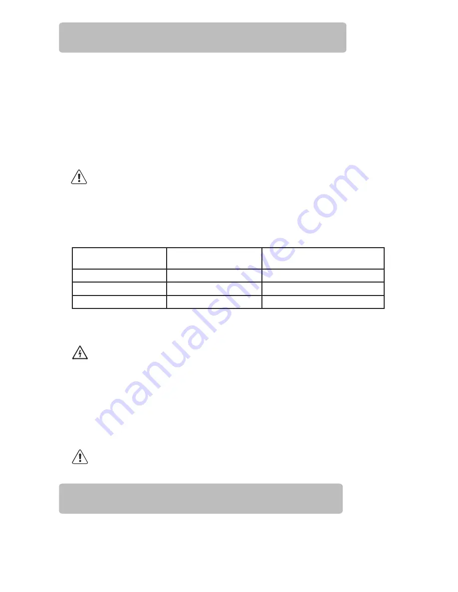
START PRESSURE
MAX. OPERATING
HEIGHT
MAX. PUMP PRESSURE
GREATER THAN
22 PSI
33 ft
44 PSI
29 PSI
49 ft
51 PSI
36 PSI
66 ft
58 PSI
WARNING: The maximum operating height between the pump and the highest point in the
system will depend on the pump start pressure setting. The maximum pressure of your pump
must exceed the value of the start pressure setting. Both these limits are specified in the table
below.
WARNING: Power supply voltages other than those specified or improper connections can
permanently damage the electronic components and will void the warranty.
This device must be assembled and installed by personnel qualified in accordance with local
laws,
regulations and codes.
1
8
.1 Water Connection (Fig.1)
The PC115A must always be installed with the arrows pointing upward, connecting the
1” threaded inlet to the pump’s outlet and the 1” threaded outlet to the point of use.
Use flexible pipes for connection to the water network, protecting the appliance form any
bending
loads and vibrations, a ball valve to isolate the pump system from the network, and a
foot valve to maintain prime for suction inlets (Fig.1).
Before starting up the unit, fill the suction inlet with water as specified in the pump’s
manual.
H07RN-F3G1.5 type cables (9 - 12 mm) or equivalent must be used in order to
ensure IP 65 protection.
The connections must be made by a qualified electrician. Install a GFCI for protection
against lethal electric shock. Be sure the circuit and device are properly grounded.
1. Check that the pump is primed properly, then partially open a tap in the user circuit.
2. Turn on power to the controller; the power LED will light up (POWER).
3. The pump will start up automatically and within 20 to 25 seconds the system should
reach approximately the maximum pressure delivered by the pump. While the
pump is running, the corresponding LED (ON) willremain illuminated.
1
9
)
Start Up:
Summary of Contents for MHP150A
Page 12: ... MHP75A MHP150A Pump ...


