background image

3

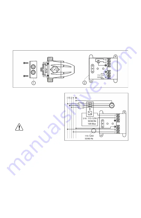
Electrical Connection

Ensure the voltage supply corresponds to the rated voltage. Remove 

the cover (faceplate) from the electronic board and make the elec-

trical connection according to the instructions shown inside. This 

controller can also be used with a single-phase pump with electrical 

demand greater than 16A, or a three-phase pump, using an auxiliary 

remote control switch (115V coil). In this case, the electrical connec-

tions must be made as shown in the diagram.


WARNING: 

Power supply 

voltages other than those 

specified or improper con

-

nections can permanently 

damage the electronic 

components and will void 

the warranty.

SOOW or H07RN-F 

type cables (.35-0.5in/ 

9-12mm O.D.) must be 

used in order to ensure 

IP65 protection.

4. STARTING AND OPERATING

Start Up

1.  Check that the pump is primed properly, then partially open a    

faucet or valve in the user circuit.

2.  Turn on power to the controller; the power LED will light up  


(Power).

3.  While the pump is running, the corresponding LED (On) will  


remain illuminated.

4.  Close the open faucet or valve. After 10- 12 seconds the pump 

will stop running, but the power supply LED (Power) will remain 

lit. Improper priming will cause malfunctions to occur.

Summary of Contents for PC115A

Page 1: ...PC115A Pump Controller USER MANUAL ...

Page 2: ...er pumps whenever a tap or valve connected to the installation is opened or closed respectively When the pump is started it keeps running as long as any connected tap remains open supplying the network with the required flow at the related pressure TABLE OF CONTENTS 1 Diagram 1 2 Physical Characteristics 2 3 Installation 2 4 Starting and Operating 3 5 Performance Specifications 5 6 Friction Loss 6...

Page 3: ...ccordance with local laws Install a GFCI grounded circuit Handle with care Impact can damage the product Before installation make sure the unit shows no visible signs of damage Water Connection The PC115A features an internal check valve and must be installed with the arrows pointing upward connecting the 1 threaded inlet to the pump s outlet and the 1 threaded outlet to the point of use with the ...

Page 4: ...voltages other than those specified or improper con nections can permanently damage the electronic components and will void the warranty SOOW or H07RN F type cables 35 0 5in 9 12mm O D must be used in order to ensure IP65 protection 4 STARTING AND OPERATING Start Up 1 Check that the pump is primed properly then partially open a faucet or valve in the user circuit 2 Turn on power to the controller ...

Page 5: ... a faucet or valve to discharge the pressure 4 Adjust the screw clockwise to increase or counter clockwise to decrease the start pressure 5 Supply power to the controller if you are not satisfied with the adjustment repeat the operations described above until you obtain the desired pressure value Operating Pressure The maximum pressure of the pump closing contact pressure and the minimum start pre...

Page 6: ...ation without manual intervention For example the pump has a water failure after five minutes of low water it will do a 25 second reset attempting to prime the pump If it is able to prime the pump the failure will clear and the pump will resume normal operation However if the failure persists the system will attempt to reset every 30 minutes for 24 hours If unable to reset the system will require ...

Page 7: ...t it the pump should start if it does not replace the controller board The pump keeps stopping and starting There is a small leak in the delivery pipe line check for any leaking taps or running toilets The pump does not stop Water loss exceeding 0 8 GPM Make sure that all the taps along the pipeline are closed and that there are no leaks The electrical connection is incorrect refer to the instruct...

Page 8: ...RainHarvest Systems RainHarvest com 800 654 9283 090220 ...

Reviews: