background image

9 |

P a g e

Installation 

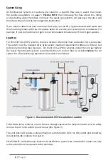
Step 1:   The reactor can be installed either horizontally or 

vertically using the clamps provided. Vertical installation is 

the  preferred  method  with  the  inlet  at  the  bottom  (lamp 

connection at the top) as it allows any air that may be in the 

lines to be easily purged from the system.

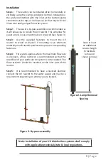
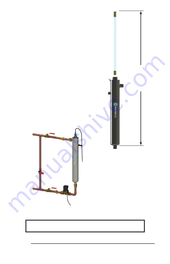
Step 2:  The use of a by-pass assembly is recommended as 

it will allow you to isolate the UV reactor. This will allow for 

easier access in case maintenance is required (See Figure 3).

Step 3:  Use  the  supplied  fasteners  to  mount  the  UV 

reactor  to  wood  or  drywall.  If  mounting  to  an  alternate 

material you will need to purchase the proper corresponding 

fasteners.

Step 4:   For water supplies where the maximum flow rate 

is unknown, a flow restrictor is recommended so that the 

rated flow of your particular UV system is not exceeded. The 

flow restrictor should be installed on the inlet port of the 

reactor.

Step 5:   It  is  recommended  to  have  a  licensed  plumber 

connect the UV reactor to the water supply and may be a 

requirement depending on where you are located. 


Figure 3.  By-pass assembly

Note: Installation of your UV disinfection systems shall comply 

with applicable provincial/state & local regulations.

Figure 2. Lamp Removal 

Spacing

leave at least 

an additional 

reactor length 

to facilitate 

lamp and 

sleeve removal

Summary of Contents for RF4 Series

Page 1: ...2 gpm RF4 5C RF5 5C RF6 5C 5 gpm RF4 3 RF5 3 RF6 3 3 gpm RF4 10C RF5 10C RF6 10C 10 gpm RF4 6 RF5 6 RF6 6 6 gpm RF4 15C RF5 15C RF6 15C 15 gpm RF4 11 RF5 11 RF6 11 11 gpm RF4 25C RF5 25C RF6 25C 25 gp...

Page 2: ...ater supply with a UV system gives you reassurance that your family will haveaccesstosafedrinkingwaterthroughoutyourentirehomewithnochanceofmicrobiological contamination This is chemical free process...

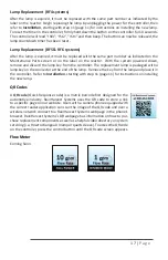
Page 3: ...5 RF6 Controllers 14 RF5 RF6Power up Sequence 14 RF5 Operational Screens 15 RF6 Operational Screens 15 Lamp Countdown Sequence 16 Lamp Replacement RF4 systems 17 Lamp Replacement RF5 RF6 systems 17 QR...

Page 4: ...vice instructions if required 7 Do not use this system for any purpose other than what it was intended for Misuse of this system could potentially cause harm to the user or others 8 Your system is int...

Page 5: ...ment required will depend on parameters being treated Hardness 7 gpg 120 mg L if hardness level is 7 gpg or slightly below the quartz sleeve must be cleaned periodically in order to ensure effi cient...

Page 6: ...026 Teflon Plug 310040 O Ring 390007 Brass Nut RF S1 RF4 RF5 RF6 06 10 15 series RF S2 RF4 20 RF5 20 RF6 20 series GLAND NUT O RING SLEEVE SPRING QUARTZ SLEEVE REACTOR UV LAMP 320006 310038 RF L210 02...

Page 7: ...omplete Assembly 310026 Teflon Plug 310040 O Ring 390007 Brass Nut RF S3 Standard series 260004 North American 260005 Euro 260006 British 260008 Australian New Zealand 320006 310038 RF L210C 05 series...

Page 8: ...s choose a location where the main cold water line is accessible The system must be installed after other water treatment equipment softener or filters but before any branches See Figure 1 For Point o...

Page 9: ...rywall If mounting to an alternate material you will need to purchase the proper corresponding fasteners Step 4 For water supplies where the maximum flow rate is unknown a flow restrictor is recommend...

Page 10: ...OTE DO NOT install a UV lamp inside the quartz sleeve without the sleeve spring in place Step 8 Install the UV sensor RainHarvest Systems systems only Align the flat portion so it faces the gland nut...

Page 11: ...The key will plug into the lamp key port on the right side of the controller Figure 8 Step 13 Plug the LUMI Loc lamp connector into the lamp Note the keying for proper alignment see Figure 7a 7b Inse...

Page 12: ...At a minimum the quartz sleeve should be cleaned on an annual basis The following steps outline a basic cleaning procedure Step 1 If a by pass assembly is installed shut the inlet valve off to preven...

Page 13: ...out of the sensor port Step 6 Holding the sensor in your hand wipe the flat portion sensor face of the sensor with isopropyl alcohol using a clean lint free cloth Step 7 Replace sensor following step...

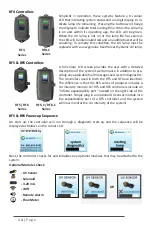
Page 14: ...a detailed description of the system s performance in addition to pro viding any applicable fault messages and system diagnostics The controllers used in both the RF5 and RF6 are identical The differ...

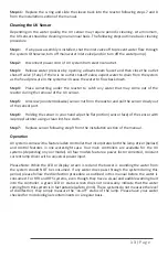
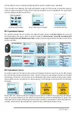
Page 15: ...ns by pressing the button located on the front of the controller RF6 Operational Screens On systems with the UV monitor the system will display the same screens as on the RF5 except the UV Intensity r...

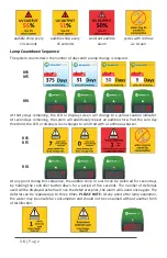
Page 16: ...ible chirp Past the zero day threshold the LED or display screen changes to solid red with a continuous buzzer RF6 RF5 RF4 At any point during this sequence the audible chirp or alarm can be deferred...

Page 17: ...ard the lamp key from the controller The replacement lamp is packaged with a lamp key on the connector at the end of the lamp Remove the key from the lamp and place it in the controller Refer to Insta...

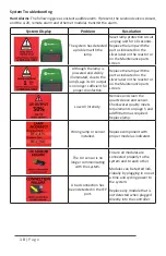
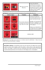
Page 18: ...er sufficient for proper disinfection Replace the lamp with the part as indicated on the silver label on the reactor or on the Maintenance parts screen Low UV Intensity Remove and clean the quartz sle...

Page 19: ...tem and to each other Modules can be tested indi vidually by plugging in one at a time and cycling power to the system Replace any module that is not detected when plugged directly into the controller...

Page 20: ...allow fresh cooler water to enter the system The TRV works without power and comes complete with 10 of drain line Order PN RF TRV 0 5 for 1 2 ports PN RF TRV 0 75 for 3 4 ports PN RF TRV 1 for 1 port...

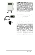
Page 21: ...F 4 20 mA MODULE Outputs a 4 20mA signal of the UV output to a remote device such as a data logger or computer Order PN MOD 420 RF The WiFi module and accompanying IoT application allows you to connec...

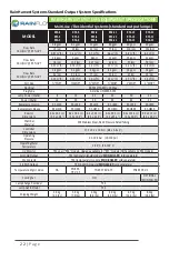
Page 22: ...P Lamp Power Watts 8 15 22 39 50 42 Power Watts 14 20 30 49 62 51 Replacement Lamp RF L210 RF L290 RF L470 RF L820 RF L999 RF L850 Replacement Sleeve RF Q210 RF Q290 RF Q470 RF Q820 RF Q999 RF Q850 Re...

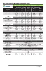
Page 23: ...pm 30 lpm 0 2 m3 hr 0 5 m3 hr 0 6 m3 hr 1 1 m3 hr 1 8 m3 hr Port Size MNPT MNPT 1 MNPT 1 MNPT 1 MNPT Electrical 90 265V 50 60Hz 1 5A Max Plug Type American NEMA 5 15P Lamp Power Watts 18 34 45 67 101...

Page 24: ...ystems will not be liable for any costs of removal installation transportation or any other charges which may arise in connection with a warranty claim Products which are sold but not manufactured by...

Page 25: ...F ANY OTHER WARRANTY TO THE EXTENT ALLOWED BY APPLICABLE LAW ANY AND ALL EXPRESS OR IMPLIED WARRANTIES NOT SET FORTH HEREIN ARE WAIVED AND DISCLAIMED INCLUDING ANY IMPLIED WARRANTY OF MERCHANTABILITY...

Page 26: ...2 6 P a g e...

Page 27: ...2 7 P a g e...

Page 28: ...PN 910336 Version Date 04 2019 RainHarvest Systems LLC 4475 Alicia Lane Cumming GA 30028 Tel 800 654 9283 www rainharvest com sales rainharvest com...

Reviews: