background image

20

Summary of Contents for RBH-4634 BF

Page 1: ...BUILT IN HOB USER MANUEL...

Page 2: ...anufacturer or its publication resulting from the incorrect use of the device to people to environment or other materials can not be held liable for damages This manual also applies to other models Di...

Page 3: ...ity without any prior notice The figures in guide are schematic your product may not match exactly Values stated on the markings of the appliance or in the other printed documents supplied with the ap...

Page 4: ...compliance with the eco design requirements the measurement methods and calculations of the following standards were applied EN 30 2 1 The information in the product data sheet is given in accordance...

Page 5: ...system Never clean your oven with vapor steam cleaners CAUTION In case of hotplate glass breakage shut immediately off all burners and any electrical heating element and isolate the appliance from the...

Page 6: ...tyrene etc where children can get at them as they can be dangerous Safety about Gas Studies Any work done on gas equipment and systems must be performed by competent and qualified persons Before insta...

Page 7: ...pliance WARNING Prior to installation ensure that the local distribution conditions nature of the gas and gas pressure and the adjustment of the appliance are compatible WARNING The adjustment conditi...

Page 8: ...pends on the degree of kitchen units and surface polish performance Bench should be flattened and located horizontally Cut the gap to be opened for hob over the bench according to the installation dim...

Page 9: ...s regarding ventilation Installation and Connections These procedures should be done exclusively by a qualified technician Installation Please carefully check the following forms and instructions to s...

Page 10: ...10 WARNING Making connection to different holes is inconvenient in terms of security as it can damage the gas and electric system Figure 2 Figure 3...

Page 11: ...11 Connection type for 20 30 40 mm bench Point A Connection holes...

Page 12: ...12 Connection type of sealing ring...

Page 13: ...he clamp to the hose Then connect the hose to oven Finally tighten the clamp with a screwdriver See Figure 4 Repeating the same procedure for the other ends of the hose and connect the tube Make sure...

Page 14: ...be longer than 200 cm for your safety Please note that the suitability of the connection record 1 2 must be Metal seals use the combination according to the standards See Figure 5 During the gas conn...

Page 15: ...bustness control See Figure 6 Figure 6 1 Hob 2 Hose nozzle 3 Hose 4 The Clamp 5 Oven Tightness Control of Part Connection Ensure that all of the buttons are off on the product Be sure that the gas is...

Page 16: ...d for gas types to be used See Table 1 Tighten injectors properly IMPORTANT Tightening the injector too much causes to become worn and occur gas leakage for this reason do not force too much when you...

Page 17: ...hould be made only by licensed electric technician in accordance with the applicable law and regulations Connections must be in accordance with national regulations Electr c Connect on Device Before W...

Page 18: ...sion cord However certainly for the adapter and power should not exceed the specified maximum current capacity The electrical safety of the appliance can only be guaranteed when it has been correctly...

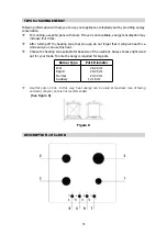
Page 19: ...use do not forget that it will give heat for a while and you can use this heat Choose the heating zone suitable for base size of the used pot Always choose right sized pot for your foods Too much ener...

Page 20: ...20...

Page 21: ...21...

Page 22: ...22...

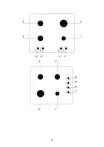
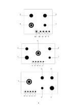
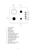
Page 23: ...R 6 HOT PLATE 145mm 7 AUXILIARY BURNER CONTROL KNOB 8 SEMI BURNER CONTROL KNOB 9 BIG BURNER CONTROL KNOB 10 SMALL WOK BURNER CONTROL KNOB 11 BIG BURNER CONTROL KNOB 12 HOT PLATE CONTROL KNOB 13 TIMER...

Page 24: ...gure 9 Firing the Heating Zones On control panel there are buttons equal to burner numbers and a marking which enables their use This marking show that related button controls which burner Your hob is...

Page 25: ...o not try to fire again the burner at least within 1 minute In this position wait a moment so the gas comes and the hob fires After seeing the flame go on switching left and to marking so the lighter...

Page 26: ...lit stop operating the device and open the compartment door and or wait at least one minute before attempting a further ignition of the burner In the event of the burner flames being accidentally ext...

Page 27: ...imer knob by turning the knob clockwise direction After the time selected ignite the burner by pushing the related gas tap knob specified at sign and turning it anti clockwise direction Flame will con...

Page 28: ...le 2 Knob Position Heat Intensity Possible Cooking Processes 0 Off Off 1 Slow Keeping food warm 2 Medium Cooking vegetables soups etc 3 High Cooking Boiling Table 2 The hotplates may be equipped with...

Page 29: ...ould be smooth and solid This ensures optimum use of the heat radiation See figure 11 Figure 11 Do not use a pan with convex or concave bottom The base of the pan must be dry Never place pans with wet...

Page 30: ...e Seran Surface Top Stove Seran Vitro ceramic surface is heatproof and is not affected from high temperature differences Do not use Seran surface as a surface to put or cut something on it Only use st...

Page 31: ...cleaned with dishwashing liquid and warm water and a soft cloth or sponge Dry it with a dry cloth Make sure that the hob body and grooves are clean and dry Unplug before any cleaning process Wait for...

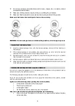
Page 32: ...n that is parallel to the ground During transport tighten with band the burner parts and pot holders inside the hob Wrap with thick carton or balloon bubbly package and tighten with band in order to a...

Page 33: ...switches Put the pan to the center of the hob pans and pots should not align with the switches Yellowing is occurring on hob plate If there is a section operating electrically in your hob yellowing ma...

Page 34: ...34 35 37 41 47 47 52 53 53 54 60 67 68 69...

Page 35: ...ar NG G20 20 mbar LPG NG wok 3 00 kW Hs 240 g h 3 15 kW Hs 0 298 m h wok 2 50 kW Hs 210 g h 2 60 kW Hs 0 251 m h 2 50 kW Hs 210 g h 2 60 kW Hs 0 251 m h 1 55 kW Hs 121 g h 1 65 kW Hs 0 156 m h 0 90 kW...

Page 36: ...36 RAINFORD RB 4654 BF RB 4634 BF 4 EE 61 0 EE 62 0 EE 62 0 EE 61 6 EN 30 2 1 66 2014 2009 125 EC RAINFORD RB 4755 BFW RB 2705 FW RB 2715 FW 4 EE 61 0 EE 62 0 EE 62 0 EE 61 0 EE 62 0 EE 61 5 EN 30 2 1...

Page 37: ...37 66 2014 2009 125 EC RAINFORD RB 4614 BW RB 2614 FR 4 EE 62 0 EE 62 0 EE 61 0 EE 61 6 EN 30 2 1 8...

Page 38: ...38...

Page 39: ...39...

Page 40: ...40 CO...

Page 41: ...41...

Page 42: ...42 2 3 100 C 30 1 min 30 mm...

Page 43: ...43 1 5 100 2 5 10 50 2 10 65 c 2 A C E 1...

Page 44: ...44 2...

Page 45: ...45 3 20 30 40 A...

Page 46: ...46...

Page 47: ...47 125...

Page 48: ...48 4 LPG 4 1 LPG 2 1 4 5 200 1 2 5...

Page 49: ...49 5 6...

Page 50: ...50 6 1 2 3 4 5 1...

Page 51: ...51 LPG G 30 30 mbar wok wok 0 95 0 85 0 85 0 65 0 50 NG G 20 20 mbar wok wok 1 35 1 15 1 15 0 97 0 72 1...

Page 52: ...52 N L 7 7...

Page 53: ...53 wok wok 26 30 24 26 c 20 22 c 12 18 c...

Page 54: ...54 8 8...

Page 55: ...55...

Page 56: ...56...

Page 57: ...57...

Page 58: ...58...

Page 59: ...59 1 2 3 4 WOK 5 WOK 7 8 9 10 WOK 11 WOK 13 14 15 16...

Page 60: ...60 9 9 10 10...

Page 61: ...61 3 4 3 4 1 1 3 5 15...

Page 62: ...62 15 1 wok wok wok wok wok wok WOK...

Page 63: ...63 0 90 Wok wok...

Page 64: ...64 0 2 0 1 2 3 2 10 15 11...

Page 65: ...65 11 3 145 150 200 3...

Page 66: ...66...

Page 67: ...67...

Page 68: ...68...

Page 69: ...69...

Page 70: ...70 WEEE 2012 19 U...

Page 71: ......

Page 72: ......

Reviews: