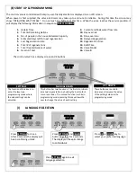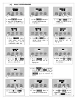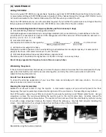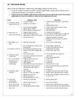
11
(G)
MAINTENANCE
Adding POT-PERM
Your unit requires POT-PERM on a regular basis. Typically, a jug (5 lbs) of POT PERM should last three to four months
or more before refilling with POT PERM powder is required. Fill the chemical tank with a full jug of POT-PERM. You do
not need to add water to the chemical tank except the first time when you install the unit.
Check the POT PERM level once a month and add as required. If you find that the water level is much higher than the
felt pad, please call Rainfresh customer care. POT PERM can be ordered from the same retailer
How to calculate Regeneration Frequency (Factory set for once every 3 days)
a)
Calculate KMnO
4
(Potassium Permanganate) demand
Multiply Manganese concentration by 3 and Hydrogen Sulphide (H
2
S) concentration by 5 and add these to the Iron
concentration. For example if Iron level is 2 PPM, Manganese is 0.5 PPM and H
2
S is 1 PPM, then KMnO
4
demand = 2 +
(3 x 0.5) + (5 x 1) = 2 + 1.5 + 5 = 8.5 PPM
b)
Calculate Unit Capacity
Unit capacity in US Gallons is then given by:
37,850___________ = 37,850___ = 1,176.4 US Gal
KMnO
4
demand x 3.785
8.5 x 3.785
c)
Estimate water usage in the home
Multiply the number of people in the house by 60 to get estimated water consumption per day. For example for 4
people in the house, total water consumed = 4 x 60 = 240 Gal.
d)
Calculate Regeneration frequency (days between regenerations)
Therefore system should be set to regenerate = 1176/240 = 4.9 days = once every 4 days.
Do not change regeneration frequency to more than once every 4 days.
Winterizing the system
If the unit is to be winterized, the best way is to close the by-pass valve and unscrew the 2 screws adjacent to the by-
pass valves that hold the unit and the by-pass valve together, and carry the unit to a place where it will not be
subject to freezing temperatures.
Care of Your Greensand filter
To retain the attractive appearance of your new filter, clean occasionally with mild soap solution. Do not use
abrasive cleaners, ammonia or solvents.
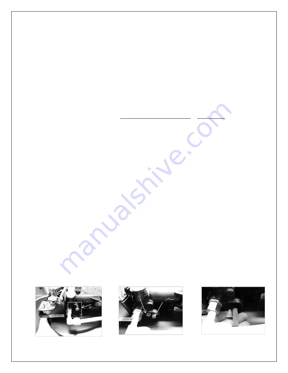
Cleaning the Injector Assembly
Sediment and silt will restrict or clog the injector. A clean water supply and pure salt will prevent this from
happening. The injector assembly is located on the right side of the control valve. This assembly is easy to clean.
Shut off the water supply to your filter and release the pressure by opening a cold filtered water faucet. Using a
screwdriver, remove the two screws holding the injector cover to the control valve body. Carefully remove the
assembly and disassemble as shown below. The injector orifice is removed from the valve body by carefully turning
it out with a large screwdriver. Remove the injector throat the same way. Carefully flush all parts including the
screen. Use a mild acid such as vinegar to clean the small holes in the orifice and throat.
Reassemble using the reverse procedure.
Injector
Screen
Summary of Contents for CGFE948
Page 13: ...13 PARTS LIST...


