12
(H)
TROUBLESHOOTING
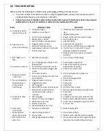
Please review the following troubleshooting guide before calling customer service.
If you are unable to resolve the problem using the guide below, please call customer service at
1800 667 8072 (Mon to Fri 8:30 AM to 5 PM EST)
Please have your receipt & model number ready before you call. Customer service may request
digital pictures of your installation in order to help troubleshoot the unit.
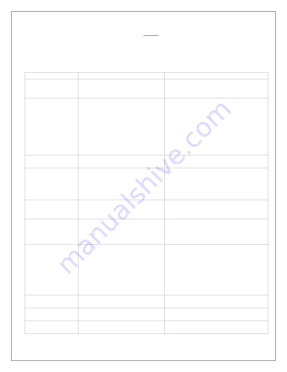
ISSUE
POSSIBLE CAUSE
SOLUTION
A.
Unit fails to start a
regeneration cycle
1.
No power supply
2.
Defective circuit board
1.
Check electrical service & re-set time of
day
2.
Replace faulty parts
B.
Filter does not
seem to be working
1.
Control valve unplugged
2.
Bypass valve is closed
3.
No POT-PERM in chemical tank
4.
Plugged injector/screen
5.
Brine refill settings wrong
6.
Leak between valve and riser tube
7.
Internal valve leak
1.
Plug in control valve to power supply
2.
Open bypass valve
3.
Add POT PERM
4.
Clean parts (see page 12)
5.
Correct brine refill settings (see page 11)
6.
Check if riser is cracked or O-ring is
damaged. Replace faulty parts
7.
Replace valve seals, spacer and piston
assembly
C.
POT PERM use is
high
1.
Refill time is too high
1.
Correct brine refill settings
D.
Low water pressure
1.
Iron or Manganese buildup in line
feeding filter
2.
Iron buildup inside valve or tank
3.
Inlet of control valve plugged due
to dirt
1.
Clean/replace supply line
2.
Clean control valve & increase
regeneration frequency
3.
Clean control valve inlet
E.
Greensand media
in drain line
1.
Air in water system
2.
Incorrect or missing drain line flow
control (DLFC)
1.
Check well system for proper air
elimination
2.
Check and replace DLFC
F.
Too much water in
chemical tank or
chemical tank
overflowing
1.
Plugged injector or screen
2.
Plugged brine valve
3.
DLFC plugged
4.
Brine float has been incorrectly set
1.
Clean parts
2.
Clean parts
3.
Clean DLFC
4.
Set brine float to mark
G.
Unit fails to draw
chemical
1.
Elastic band on safety float in
chemical tank has not been
removed
2.
DLFC plugged
3.
Injector or screen is plugged
4.
Inlet pressure too low
5.
Internal valve leak
6.
Vacation Mode set to “Yes”
1.
Remove elastic band as per instructions
2.
Clean DLFC
3.
Clean parts
4.
Increase min pressure to at least 25 psi
5.
Replace seals, spacer & piston assembly
6.
Under level 1 programming, set vacation
mode to “No”
H.
Unit cycles
continuously
1.
Defective circuit board
1.
Replace faulty parts
I.
Water flows to
drain continuously
1.
Valve settings incorrect
2.
Internal leak
1.
Check valve settings
2.
Replace seals, spacer & piston assembly
J.
POT-PERM in the
water line
1.
Wrong regeneration settings
1.
Ensure that under level 2 programming all
parameters are set to default settings
Summary of Contents for CGFE948
Page 13: ...13 PARTS LIST...


