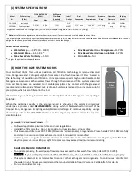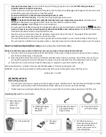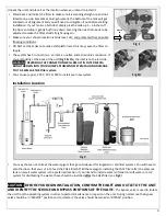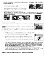
6
Remove the elastic band from the float assembly inside the chemical tank. DO NOT REMOVE WHITE FELT PAD FROM
INSIDE THE CHEMICAL TANK.
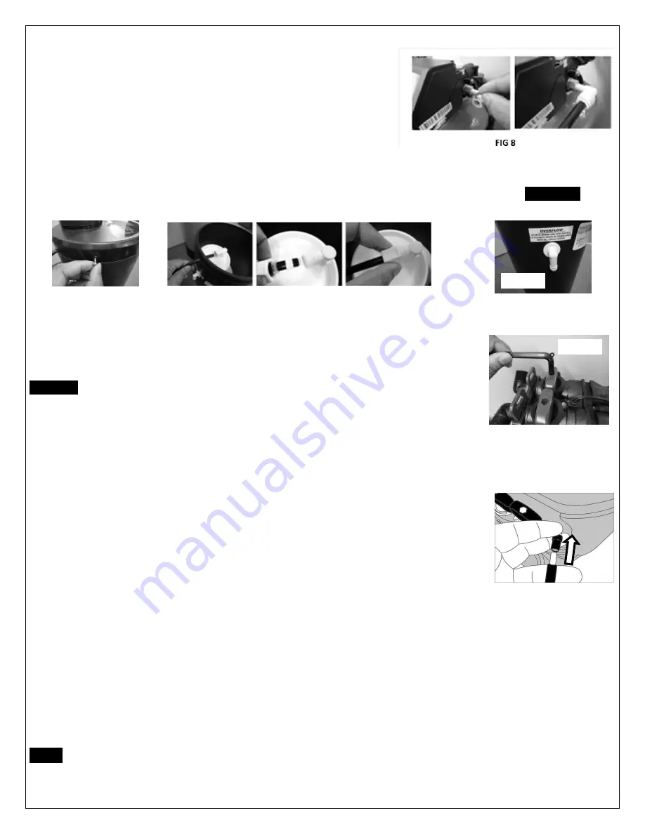
Remove the locking clip on the brine fitting & insert one end of the
3/8" tubing
(included)
into this fitting all the way until the tube can go
in no further. Replace the locking clip (
Fig 8).
Remove the top lid of the chemical tank. The other end of the tubing
goes through the small hole near the top of the chemical tank (
Fig 9)
.
Bring the end of the 3/8" tubing into the brine well and make the
connection with the compression fitting on the safety float.
The barbed elbow near the middle of the chemical tank (
Fig 10)
is for a "gravity" overflow line in case of a malfunction
resulting in a tank overflow. This must be run to drain. It uses the same size tubing as the drain line.
WARNING :
DO
NOT TEE THESE TWO TOGETHER.
Add the chemical (Pot-Perm)
The bottom of the chemical tank has a felt pad.
DO NOT REMOVE THIS FELT PAD.
With a
bucket or hose, pour approximately 1 gallon of water into the chemical tank. The exact level is
not critical, but be careful not to overflow the tank.
CAUTION:
Before adding POT PERM, please check safety instructions included with the POT-
PERM jug and label.
Pour the entire 5 lb jug of POT PERM into the chemical tank (included with
model CGFE948). The powder stays above the felt pad while the water/Pot Perm solution stays
below it. Typically, five pounds of POT PERM should last three to four months or more before
refilling with POT PERM powder is required.
Insert Allen key into the bypass handles and make sure that the valve is in BYPASS position
Turn on the switch for the well pump. If you had emptied the pressure tank, allow it to
fill up until the well pump shuts off. Slightly open the main shut-off valve.
Insert the Allen key into the inlet side of the bypass valve (
Fig 11
) and turn it on only
slightly and watch for leaks. Now insert Allen key to outlet side of the bypass valve and
turn it on slightly. Make sure a faucet is on somewhere and that any aerator is removed
to avoid clogging from loosened scale in the pipes. Leave the bypass valve in the same
position and slowly turn the main shutoff valve on all the way. If you have no leaks,
proceed to the next steps.
Connect the control valve to the AC power source. Turn the bypass valve (both knobs) slightly more into the service
position to allow water to run into the unit.
You want water to initially fill the tank slowly. Once the tank is full of
water, you can open bypass valve fully. This prevents filter media from being pushed up into the control head by
the initial surge of water going in.
Water may look somewhat discoloured at first. This is normal. Once the water
runs clear and free from air pockets, turn the bypass valve fully into the "service position".
Your water may be discoloured for a day to two after initial installation or may have small air bubbles. This is
normal. Also, it will take a few days to get all the untreated water out of your hot water tank and you may choose to
empty your hot water tank at the time of installation and clean it before letting water in from the filter.
NOTE:
Your unit is not yet ready for service until you complete manual regeneration
Fig 11
Fig 9
Fig 10
Summary of Contents for CGFE948
Page 13: ...13 PARTS LIST...


