background image

4


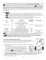
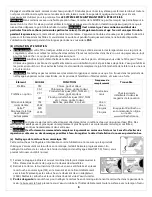
Step 1: Mounting the Faucet 

Faucet may be installed in existing hole in sink if available or in counter top.  

Note:

 The faucet may also be installed in the sink sprayer hole if available.  

1.


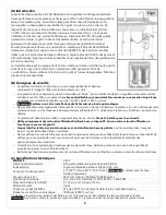
Position faucet on counter top beside sink in desired position. Ensure that swivel spout will 
extend over sink and that there is room under the counter for faucet shank and to tighten 
nuts. 

2.


Mark the location and drill a ½” hole (Fig 2). Protect your laminate counter top by applying 
a layer of masking tape and use a sharp drill bit. 

Caution:


For granite or other stone 

countertops, hole should be drilled only by a professional. Do not attempt to do this 
yourself to prevent breakage. 

3.


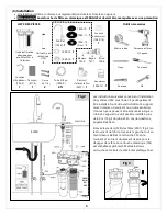
Insert faucet shank through escutcheon washer (1050-10), and then through counter top 
(See Fig 4). From under the sink, install 1050-11 large washer, plastic washer (1050-12), metal lock washer (1050-13) 
and locking nut (1050-14) as shown in fig 3. Using a wrench, tighten locking nut securely while someone holds the 
faucet body so it does not turn. Place adaptor washer (1040-16) inside 3/8” adapter (1040-15) (Fig 4) and tighten 
adaptor securely on to the faucet shank with a wrench. 

Note

:

 Do not use any thread sealant or tape on the faucet 

shank.  


Step 2: Mounting the Unit 

1.


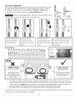
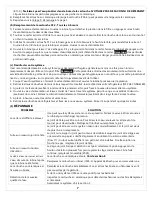
Locate best position for mounting unit undersink near faucet. Mark mounting 
bracket screw locations using mounting bracket (2565) as a template (Fig 5). 
Use a level to align holes parallel to cabinet base. 

Note:


LEAVE 

MINIMUM OF 

18 INCHES 

CLEARANCE from the top edge of the bracket to the cabinet floor. 

THE HIGHER AND CLOSER TO THE FRONT YOU MOUNT THE UNIT THE 
BETTER FOR REGULAR MAINTENANCE.  

2.


Partially screw the 2 mounting bracket screws (1011-0) into screw locations. Install mounting bracket and head 
assembly over screw heads. Use a level to make sure bracket is level and tighten screws. 

Note:


If wall is too thin to 

accept screws then use round head nuts and bolts (not supplied) to mount bracket. 


Step 3: Connecting the faucet 

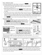
Measure and cut a length from plastic tubing (1009-0) to 
connect faucet to the OUTLET fitting (2553). Make sure to 
leave enough tube for connecting supply valve to INLET. 

Note:

 Use only a sharp knife to cut the tube straight   

(Fig 6). Using a saw or cutting the tube at an angle can 
cause the fitting to leak. 


Slide compression nut (720-0) and compression sleeve (721-1) (with narrow end towards faucet) 
onto tube and put tube insert (722-0) into tube as shown in Fig 7. Push tube into end of adaptor 
(1040-15) and hold firmly in place. Now tighten nut securely with a wrench. Pull tube to check secure connection. 


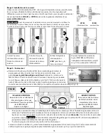
Remove the red clip on the OUTLET Acculink

TM

 fitting (2553) and connect the other end of tubing to it by pushing the tube 

into the fitting until it touches the tube stop and cannot go in any further (Fig 8A). Replace lock ring. Push the remaining 
tube into the INLET fitting the same way. 

Note:


To remove tubing from the fitting, press the collet in with two fingers while 

pulling tube out (Fig 8B). Without pressing the collet, the tubing will stay locked in position. Pull tube to check secure 
connection. 

FIG 5 


FIG 8A 

FIG 8B 

FIG 6 

FIG 4 

FIG 7 

Summary of Contents for UCS2

Page 1: ...o CSA Standard B483 1 to NSF ANSI Standard 53 for reduction of Cyst e g Cryptosporidium Giardia and lindane to NSF ANSI Standard 42 for reduction of chlorine taste odour and to NSF ANSI 372 The standa...

Page 2: ...regulator setting is 75 psi 5 1 bar 517 kPa or less o Note Do not install in multi storey buildings over 4 storeys o Do not subject to freezing temperatures with water inside the unit If your unit wil...

Page 3: ...t should not be installed more than fifteen feet away from the faucet Call Rainfresh if you have questions Remove each sump 520 by turning it 1 8 turn left then pulling away from head 2501 Fig 3 Remov...

Page 4: ...NIMUM OF 18 INCHES CLEARANCE from the top edge of the bracket to the cabinet floor THE HIGHER AND CLOSER TO THE FRONT YOU MOUNT THE UNIT THE BETTER FOR REGULAR MAINTENANCE 2 Partially screw the 2 moun...

Page 5: ...g up Align the sump under the filter head and pull the cartridge up with one hand and push the cartridge seal into the boss of white head outlet side Pull sump and lock into position Fig 9 Note Bottom...

Page 6: ...odour VC1 Chemicals VOC THM etc chlorine taste and odour LR1 Lead chemicals VOC THM etc chlorine taste and odour Ceramic filter 1M Bacteria parasites E coli etc 1 year Head seals 2502 1 year Sump 520...

Page 7: ...un some water through the system until you smell the bleach coming out of the faucet Turn off faucet immediately and let bleach stay in the system Turn OFF the supply valve 5 After 4 6 hours open sump...

Page 8: ...y shall consist of repair replacement or credit at its option of any part found by the Company inspection to be defective provided that the product has not been misused abused altered or damaged as de...

Page 9: ...infresh Nous nous engageons vous donner enti re satisfaction Si vous avez des questions lors de l installation de l utilisation ou de la maintenance de votre nouveau syst me ne retournez pas au magasi...

Page 10: ...ts de plus de quatre tages o Ne pas exposer des temp ratures inf rieures 0 C lorsqu il y a de l eau l int rieur du syst me Si vous n utilisez pas votre syst me en hiver ou s il est expos des temp ratu...

Page 11: ...ll plus de 4 5 m 15 pi du robinet En cas de questions appelez Rainfresh Enlevez les carters 520 des t tes 2501 Fig 3 en les tournant de 1 8 de tour vers la gauche tout en tirant dessus Retirez la cart...

Page 12: ...gabarit pour marquer l emplacement des trous Fig 5 Remarque LAISSEZ AU MOINS 18 POUCES de d gagement sous du bord sup rieur du support LE PLUS LEV ET PLUS PR S QUE VOUS MONTEZ L UNIT L MEILLEUR IL SER...

Page 13: ...vec l extr mit ouverte orient e vers le haut Alignez le carter sous la t te de filtre tirez la cartouche vers le haut avec une main et poussez le joint de la cartouche dans la t te blanche c t sortie...

Page 14: ...ou f ler les carters et causer une fuite l ment MOD LE FONCTION Fr quence de remplacement Trouvable Pr filtre CF2 Chlore go t et odeur Quatre six mois Chez les grands d taillants ou dans les magasins...

Page 15: ...CONGELER 3 Ajouter de tasse de javellisant inodore dans le premier carter puis fixez nouveau les deux carters au syst me 4 Ouvrez la valve d alimentation et laissez couler de l eau travers le syst me...

Page 16: ...d achat initial Aux termes de la pr sente garantie la soci t s engage r parer ou remplacer sa discr tion toute pi ce qu elle juge d fectueuse pourvu qu elle ne d termine pas que le filtre a t modifi o...

Reviews: