4
AND REPLACEMENT. THE HIGHER AND CLOSER TO THE FRONT YOU MOUNT THE UNIT THE BETTER FOR REGULAR
MAINTENANCE.
2.
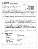
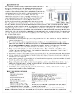
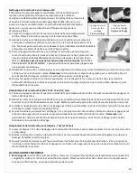
Partially screw the 3 mounting bracket screws (1011-0) into screw locations. Install mounting bracket and head
assembly over screw heads and tighten screws.
NOTE:
If wall is too thin to accept screws then use round head
nuts and bolts (not supplied) to mount bracket.
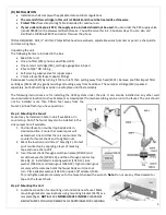
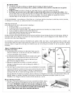
Step 3: Connecting the faucet
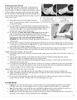
Measure and cut a length from plastic tubing
(1009-0) to connect faucet to the OUTLET fitting
(2554). Make sure to leave enough tube for
connecting supply valve to INLET.
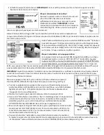
NOTE: Use only a sharp knife to cut the tube
straight (fig 4A). Using a saw or cutting the tube
at an angle can cause the fitting to leak.
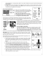
Slide compression nut (720-0) and compression sleeve (721-1) onto tube and put tube
insert (722-0) into tube as shown in Fig. 5. Push tube into end of adaptor (1040-15) and
hold firmly in place. Now tighten nut securely with a wrench.
Connect the other end of tubing to OUTLET Acculink
TM
fitting (2554) by
pushing the tube into the fitting until it touches the tube stop and cannot go
in any further (Fig. 6A). To remove tubing from the fitting, press the collet in
with two fingers while pulling tube out (fig 6B). Without pressing the collet,
the tubing will stay locked in position.
Step 4: Installing the supply valve
The self-piercing supply valve (1008-0) can be installed on copper or CPVC
rigid plastic pipe of 3/8" to 1" diameter. If your piping is PEX or any other
softer material, DO NOT USE this supply valve as it can cause leaks. For PEX,
you can purchase appropriate fittings at the same store where you purchased
this unit or you can order the supply valve kit (model CK538) from www.rainfreshstore.com
IMPORTANT:
Before you install supply valve, confirm the cold water pipe by running
hot water through your kitchen faucet. Touch both pipes under the sink to verify cold
water pipe and turn off the faucet.
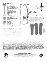
Orient saddle valve with outlet threads pointing towards INLET fitting (2553) so that
remaining length of tube will reach. (See Fig. 1)
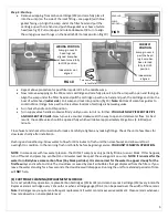
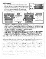
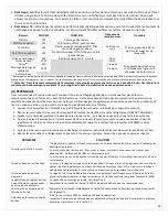
Back off handle on saddle valve. Make sure piercing tip is flush with or slightly
protruding from rubber gasket as shown in Fig. 7. If it is sticking out too far
gently push it against something flat to push it back in flush with the rubber
gasket.
Unscrew the bolts to separate the back plate from the supply valve.
With rubber gasket in position clamp entire assembly to pipe using bolts
provided. Tighten bolts, keeping brackets parallel until rubber gasket is firmly
compressed.
CAUTION: DO NOT OVERTIGHTEN. Do not turn handle yet
.
Measure and cut remaining length of plastic tubing to connect saddle clamp to
INLET fittings (2553). Slide compression nut (720-0) and compression sleeve
(721-1) onto tube and put tube insert (722-0) into tube as shown in Fig. 8
Push tube into end of saddle clamp fitting and hold firmly in place. Securely
tighten the compression nut while holding other end of fitting with a wrench. Connect other end of tubing to
INLET fitting (2553) as shown in Fig. 6A.
FIG 8


