background image


 Rainman Electric Manual 

 Page 7 

Using the system 

This section explains how to operate the system on a regular basis, including set up, starting, stopping, and 
flushing the system.  

Setup - Portable 

1.


Place  the  Rainman  Pressure  Supply  Unit  (PSU)  and  Reverse  Osmosis  (RO)  unit  in  a  stable 
place on the deck of your vessel. A swim platform is an ideal location. 

Certain positions on some vessels will resonate causing excess noise. In this case, place the 
unit on a towel or foam mat. 

Make sure the PSU is no more than 2 metres (6 feet) above water level. The unit will work 
best operating as close to water level as possible. 

Do not use on a swim platform if there is any chance of the unit getting wet. 

2.


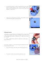
Open the RO unit. Remove and uncoil the three hoses. Remove the white travel plug from 
the quick connect on the outside of the PSU. Connect the black high-pressure hose to the 
PSU. Make sure the high-

pressure hose doesn’t chafe around hard corners.


3.


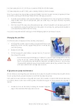
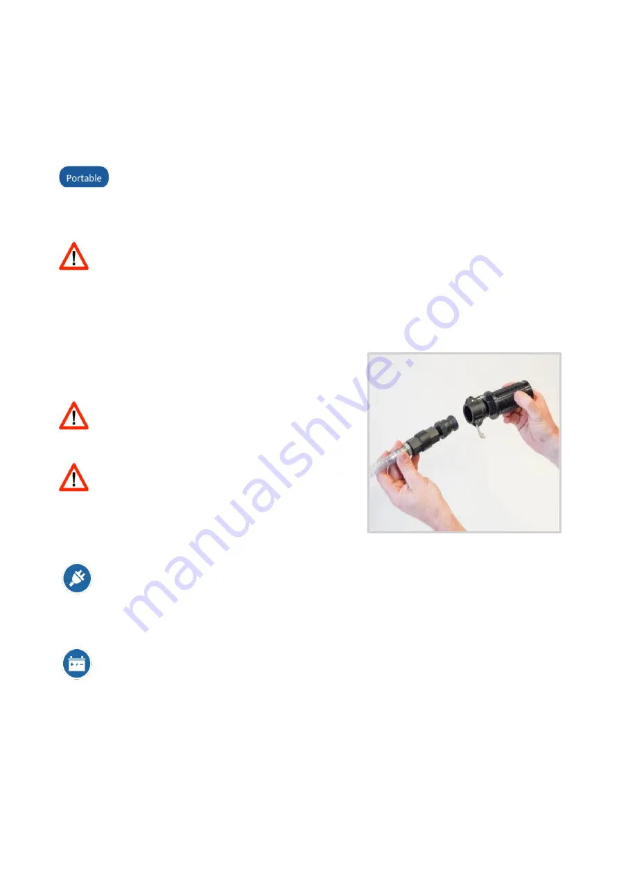
Remove the plastic spiral intake hose from the 
PSU and remove the cap. Attach the strainer to 
the end of the pickup hose. 

Starting  the  unit  with  the  cap  in  place  will 
damage the pumps.  

4.


Place the intake hose in the source water. 

Make sure the intake hose is submerged and is 
not on the sea floor or among seaweed, which 
can cause blockage. 

5.


Direct the green brine hose overboard. 

6.


Direct the white product hose overboard. Do not put it into your water tank at this stage. 

7.


Ensuring the power switch is off, plug the power cord into an AC power source. If using a 
generator, make sure it is rated to at least 2000 Watts peak, 1600 Watts continuous power. 
If using a Honda portable generator, make sure the eco-throttle is off. Once the Rainman is 
running,  you  can  switch  the  eco-throttle  back  on.  Make  sure  the  voltage  and  frequency 
match the unit (eg. 115VAC/60Hz or 230VAC/50Hz). 

Ensuring the power switch/circuit breaker is in the off position, connect the unit to a 12VDC 
power supply. During startup, the 12v PSU might draw up to 40A for a brief period and will 
settle down to 28-32A in normal operation once the motor and crank case have reached 
normal operating temperature. Therefore, it is important that the 12V supply  can support 
this current draw without a significant drop in voltage.  

Cable runs should be kept to a minimum. If an extension cable is used, it must be of sufficient 

gauge to minimise voltage drop. Several easy to use ‘voltage drop calculators’ are available 

online. 

8.


Ensure the pressure valve in the RO unit is in an open position (fully anti-clockwise). 

Summary of Contents for Electric

Page 1: ...Electric Watermaker Operations Manual Rainman Technology Pty Ltd 17 10 18 Orchard Road Brookvale NSW 2100 Australia www rainmandesal com support rainmandesal com 61 433 826 626 Version 2 81...

Page 2: ...Portable 10 Shutdown Installed 10 Desalinating while under way 11 Desalinating brackish water 12 Care and maintenance 12 Storage 12 Reverse osmosis membrane care 13 Fresh water flushing 13 Pickling y...

Page 3: ...lectric plug icon means the paragraph only applies to AC electric systems either 230VAC 50Hz or 115VAC 60Hz systems The battery icon means the paragraph only applies to the 12VDC systems This icon ind...

Page 4: ...ll amount of fresh water from the pressurised seawater stream and diverts it into your tank The bulk of the seawater goes to waste as a supersaline brine output The systems can be operated as complete...

Page 5: ...es from getting through and they are captured on the filter material When a lot of particles have been captured on the filter and it s dirty you change it In contrast to a traditional filter the RO pr...

Page 6: ...ystem for the reverse osmosis membranes to operate 4 The relief valve only opens if the control valve is closed excessively 5 A high pressure hose carries filtered seawater to the reverse osmosis memb...

Page 7: ...watermakers Various options are shown here Rainman AC naked PSU Rainman AC PSU in case Rainman 12VDC naked PSU Rainman 12VDC PSU in case Rainman petrol gasoline PSU Compact RO in case High output RO...

Page 8: ...cover from the Pressure Supply Unit by unscrewing 2 screws and lifting upwards 2 Remove the black travel oil plug from the high pressure pump using an 8mm 5 16 allen key 3 Replace with the supplied br...

Page 9: ...source water Make sure the intake hose is submerged and is not on the sea floor or among seaweed which can cause blockage 5 Direct the green brine hose overboard 6 Direct the white product hose overb...

Page 10: ...water that you suspect might be brackish See the section Desalinating Brackish Water Never allow water containing chlorine to enter your watermaker That includes town or tap water which contains chlo...

Page 11: ...he clear liquid inside the pressure gauge is glycerine This is to reduce vibration inside the gauge and ensure long and reliable service It is normal to see a large bubble inside the gauge If you are...

Page 12: ...Maintenance section below 4 Replace the cap on the intake hose to keep the unit primed during storage 5 Replace the rubber boots on each of the other hoses to keep the system clean and prevent water...

Page 13: ...by trailing the intake hose in the wash at the stern of their vessel To prevent air working into the system customers have used either weights or a down pole to hold the intake below the surface Slide...

Page 14: ...tion rate using the flow meter so as not to exceed the maximum flow rate for the membranes Rated maximum outputs PSU RO Type High Output Compact Economy AC Electric 140 lph 37 gph 70 lph 18 gph 70 lph...

Page 15: ...er flush If unused for between 7 and 30 days Pickle the system If unused for 30 days Pickle the system discard the pre filter and drain the pre filter housing Some pre filters can turn black if stored...

Page 16: ...er Start the system again keeping the pressure control valve open and run the entire contents through the system 2 When the bucket is almost empty switch off your watermaker leaving the pickling fluid...

Page 17: ...he pre filter place the Pressure Supply Unit PSU on the deck of your vessel Use the supplied filter wrench to remove the clear filter housing 2 Replace the cartridge 3 Fill the housing with water befo...

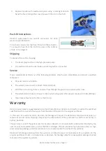
Page 18: ...Lift pump service The impeller in the brass lift pump is a consumable item We recommend inspecting the impeller for signs of wear or cracking every12 months or 500 hours and replacing if appropriate...

Page 19: ...make salty tasting water after several minutes at 55 bar 800 psi Major leaks of water in the PSU or the RO unit Warranty Rainman watermaker are guaranteed to be free of manufacturer defects and to per...

Page 20: ...id you leave any small parts of the plastic wrapping on it which may now be clogging the flow in the filter housing 4 Ensure the pre filter cartridge is only a particle filter not a combination carbon...

Page 21: ...power factor decreases causing decreased efficiency The motor starts drawing more current from the generator to do the work that is required to operate at the required pressure and flow rates This ha...

Page 22: ...tely Pressure vessel O ring failure It is not normal for an O ring on the pressure vessel to spontaneously fail If there are problems it is typically after changing the membrane Difficult to insert HP...

Page 23: ...er object The black casing is cosmetic and will not affect performance The HP hose can be replaced if it is near failure Product water flow is unexpectedly high RO membrane has failed Check salinity o...

Page 24: ...Installation Instructions Appendix 2 of General Instruction Manual Rainman Technology Pty Ltd 17 10 18 Orchard Road Brookvale NSW 2100 Australia www rainmandesal com support rainmandesal com 61 433 8...

Page 25: ...Mounting Cased Pressure Supply Unit PSU 5 Mounting Naked Reverse Osmosis RO Unit 6 Mounting Cased Reverse Osmosis RO Unit 9 Plumbing Watermaker Into Your Vessel 10 Stage 1 Seawater Intake 10 Stage 2...

Page 26: ...divided into the physical installation process and then plumbing the system into your vessel Physically Mounting Your Watermaker The mounting system is moulded from rugged fiberglass filled nylon and...

Page 27: ...temperature in a max surrounding air temperature of 40C 104F If the unit is mounted in an enclosed space without adequate ventilation the air in the space will heat to over 40C 104F very easily If you...

Page 28: ...eat taking care to align the black rubber vibration isolators on the PSU with the corresponding holes in the side frame 5 Slide the other mounting frame onto the mounting seat taking care to align the...

Page 29: ...y important that the tube from the brass lift pump runs to the IN side and the tube from the OUT side runs to the high pressure pump Note that the screws mounting the bracket to the wall are larger th...

Page 30: ...If you are mounting the PSU in an enclosure with other machinery e g in an engine room it is very important to ensure that the ambient temperature remains below 40C 104F whilst your watermaker is run...

Page 31: ...Output twin 40 membranes or Economy single 40 membrane are the same and consist of three parts One back bracket and two mounting saddles The Compact unit twin 21 membranes consists of four parts incl...

Page 32: ...o mount against a wall but the back bracket also has angled holes for mounting on a floor if desired If you have a Compact RO unit 2 x 21 membranes the abbreviated back brackets should be mounted 250m...

Page 33: ...crews hold the bracket in place and the flow meter itself slots in The hose from the RO unit inserts into the bottom of the flow meter push fit connector The hose from the top of the flow meter connec...

Page 34: ...o assist with mounting the systems while in the case Instructions 1 Place each mounting plate inside the case over the two holes in the rear Use double sided tape or other adhesive to hold the plates...

Page 35: ...o double clamp each hose barb You will need to use sealant example SikaFlex or similar on each hose barb before connecting hoses Option 1 Dedicated Through Hull If you already have a spare through hul...

Page 36: ...se for a deck water pump or similar Ensure your Rainman system is not competing for water while running with a shared through hull 1 Cut the existing 3 4 supply hose example deck wash pump and add the...

Page 37: ...hose will come from the remote pressure control valve gauge assembly Run the green brine hose from the RO unit to an above water through hull fitting cable tying along the way to secure Parts are supp...

Page 38: ...F port In the other out port Port G connect a loose hose this loose end will become your testing hose Use a sharp knife to cut the white product water hose Make sure the hose is cut straight to ensure...

Page 39: ...oflush Instructions Appendix 3 of General Instruction Manual Rainman Technology Pty Ltd 17 10 18 Orchard Road Brookvale NSW 2100 Australia www rainmandesal com support rainmandesal com 61 433 826 626...

Page 40: ...osmosis membranes The system utilises the boat s main water pump a Rainman flush timer box a motorised valve and an activated carbon filter neutralises chlorine that may be in your water tank to forc...

Page 41: ...ple it may have its own circuit or be wired to your fresh water pump circuit Plumbing The inlet side of the motorised valve connects to the fresh water supply The outlet side of the motorised valve co...

Page 42: ...e if there are three days before the next flush the blue LED will flash three times then pause and repeat This informs the user that the flush timer is powered and counting down the seven day period b...

Page 43: ...r to be pushed through on each flush cycle The best way to determine this is by measuring the brine discharge during a flush cycle and programme the timer accordingly A quick reference card summarisin...

Reviews: