


2 - GB
GB
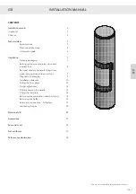
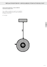
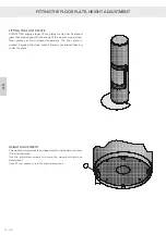
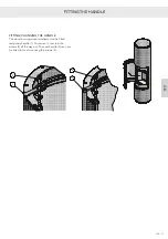
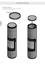
INSTALLATION MANUAL
Congratulations on the acquisition of your new RAIS or
ATTIKA product! This installation manual will ensure that
your wood-burning stove is installed correctly and that it
will provide you with comfort and pleasure for many years
to come.
IN GENERAL
It is important that the wood-burning stove is correctly
installed, in consideration of the environment and people’s
safety.
Its installation must comply with all local rules and
regulations, including those that refer to national and
European standards. A certified chimney sweeper
should be contacted before the installation is started.
No unauthorised alterations may be made to the wood-
burning stove.
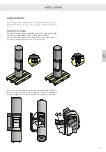
INSTALLATION REQUIREMENTS
Before the wood-burning stove may be taken into use the
installation must be reported to your local chimney sweeper.
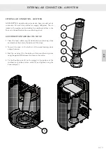
There must be the correct supply of fresh air in the installation
room to ensure good combustion – if required, through an
AirSystem connection. NB: Any mechanical air extraction, for
example a cooker hood, can minimise the supply of air.
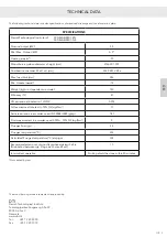
The wood-burning stove has an air consumption of at least
12.6 m3/h.
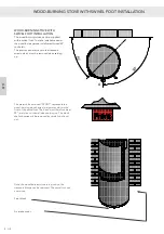
The space underneath the combustion chamber is not
suitable for the storage of flammable material unless a
reflective insulation panel is fitted!
The floor structure must be able to support the weight of
the wood-burning stove and a chimney, if required. If the
existing floor structure does not meet this requirement,
suitable measures must be taken (e.g. installation of a load
distribution plate). Seek advice from a building expert.
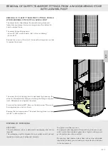
If the wood-burning stove is to be installed on a flammable
floor, national
and local regulations must be complied with,
including the size of the non-flammable plate that must cover
the floor in front of the wood-burning stove to protect the
floor from fallen embers.
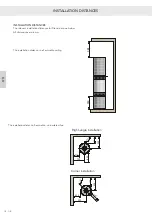
The wood-burning stove must be positioned at a safe distance
from flammable material. Due to the risk of fire, flammable
items (e.g. furniture) may not be positioned closer to the front
of the glass than the closest permitted distance stated in the
installation section. When deciding where you shall install
your RAIS/ATTIKA wood-burning stove, you should think
about being able to heat other rooms in the home, so you
get the most out of your new stove.
When your wood-burning stove is delivered, please
check it for defects.
CHIMNEY
The chimney must be high enough to ensure that the
chimney draught conditions are correct, i.e. –14 to –18
pascal. If the recommended chimney draught cannot
be achieved, problems from smoke escaping from the
door may arise when lighting the fire. We recommend
that the chimney is adapted to suit the flue outlet
spigot. The flue outlet spigot is 150 mm in diameter.
If the draught is excessive, it is recommended that you equip
the chimney with a regulating damper. If a regulating damper
is fitted, you must ensure that there is a free flow area of at
least 20 cm² at the closed regulating damper.
Remember that there must be free access to the access door
on the chimney.
INSTALLATION MANUAL
Summary of Contents for Attika Pilar
Page 2: ......
Page 7: ...B 16 0101 6550 Pilar n 0 65 245 1666 5 n166 n DK 5 DK MÅLSKITSER ...
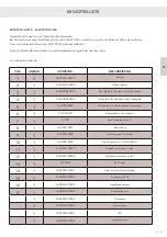
Page 32: ...RESERVEDELSTEGNING 30 DK DK 1 2 3 4 5 6 7 8 9 10 11 12 13 14 16 15 ...
Page 34: ...1 2 3 4 5 6 7 8 9 10 11 12 13 14 15 16 17 24 RESERVEDELSTEGNING 32 DK DK ...
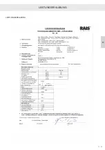
Page 36: ...34 DK DK YDEEVNEDEKLARATION YDEEVNEDEKLARATION ...
Page 41: ...B 16 0101 6550 Pilar n 0 65 245 1666 5 n166 n D 5 D MASSZEICHNUNGEN ...
Page 66: ...30 D D 1 2 3 4 5 6 7 8 9 10 11 12 13 14 16 15 ERSATZTEILZEICHNUNG ...
Page 68: ...1 2 3 4 5 6 7 8 9 10 11 12 13 14 15 16 17 24 32 D D ERSATZTEILZEICHNUNG ...
Page 69: ...D 33 D LEISTUNGSERKLÄRUNG LEISTUNGSERKLÄRUNG ...
Page 70: ...34 D D ...
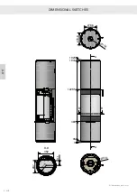
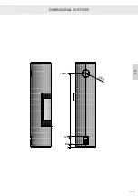
Page 75: ...B 16 0101 6550 Pilar n 0 65 245 1666 5 n166 n GB 5 GB DIMENSIONAL SKETCHES ...
Page 100: ...SPARE PARTS DRAWING 30 GB GB 1 2 3 4 5 6 7 8 9 10 11 12 13 14 16 15 ...
Page 102: ...1 2 3 4 5 6 7 8 9 10 11 12 13 14 15 16 17 24 SPARE PARTS DRAWING 32 GB GB ...
Page 103: ...GB 33 GB DECLARATION OF PERFORMANCE DECLARATION OF PERFORMANCE ...
Page 104: ...34 GB GB ...
Page 109: ...B 16 0101 6550 Pilar n 0 65 245 1666 5 n166 n F 5 F en mm SCHÉMAS COTÉS ...
Page 134: ...30 F F 1 2 3 4 5 6 7 8 9 10 11 12 13 14 16 15 ...
Page 136: ...1 2 3 4 5 6 7 8 9 10 11 12 13 14 15 16 17 24 32 F F ...
Page 137: ...F 33 F DÉCLARATION DES PERFORMANCES DÉCLARATION DES PERFORMANCES ...
Page 138: ...34 F F ...
Page 143: ...B 16 0101 6550 Pilar n 0 65 245 1666 5 n166 n NO 5 NO MÅLTEGNINGER ...
Page 168: ...30 NO NO 1 2 3 4 5 6 7 8 9 10 11 12 13 14 16 15 RESERVEDELSTEGNING ...
Page 170: ...1 2 3 4 5 6 7 8 9 10 11 12 13 14 15 16 17 24 RESERVEDELSTEGNING 32 NO NO ...
Page 171: ...NO 33 NO YTELSESERKLÆRING YTELSESERKLÆRING ...
Page 172: ...34 NO NO ...
Page 177: ...B 16 0101 6550 Pilar n 0 65 245 1666 5 n166 n S 5 S MÅTTRITNINGAR ...
Page 202: ...30 S S 1 2 3 4 5 6 7 8 9 10 11 12 13 14 16 15 RESERVDELSRITNING ...
Page 204: ...1 2 3 4 5 6 7 8 9 10 11 12 13 14 15 16 17 24 32 S S RESERVDELSRITNING ...
Page 205: ...S 33 S PRESTANDADEKLARATION PRESTANDADEKLARATION ...
Page 206: ...34 S S ...
Page 211: ...B 16 0101 6550 Pilar n 0 65 245 1666 5 n166 n SF 5 SF MITTAPIIRUSTUKSET ...
Page 236: ...30 SF SF 1 2 3 4 5 6 7 8 9 10 11 12 13 14 16 15 ...
Page 238: ...1 2 3 4 5 6 7 8 9 10 11 12 13 14 15 16 17 24 32 SF SF ...
Page 239: ...SF 33 SF SUORITUSTASOILMOITUS SUORITUSTASOILMOITUS ...
Page 240: ...34 SF SF ...
Page 245: ...B 16 0101 6550 Pilar n 0 65 245 1666 5 n166 n NL 5 NL MAATTEKENINGEN ...
Page 270: ...TEKENING MET RESERVEONDERDELEN 30 NL NL 1 2 3 4 5 6 7 8 9 10 11 12 13 14 16 15 ...
Page 272: ...1 2 3 4 5 6 7 8 9 10 11 12 13 14 15 16 17 24 TEKENING MET RESERVEONDERDELEN 32 NL NL ...
Page 273: ...NL 33 NL PRESTATIEVERKLARING PRESTATIEVERKLARING ...
Page 274: ...34 NL NL ...


