1
2
3
3
4
4
3
5
6
1
2
3
3
4
4
3
5
6
GB
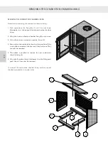
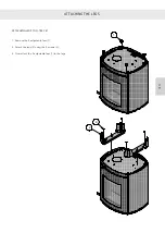
REMOVING THE COMBUSTION CHAMBER LINING
REMOVING THE COMBUSTION CHAMBER LINING
Procedure for removing the combustion chamber lining:
1. Push upwards on the flue plate (1) until it moves freely
.
Afterwards, turn it down past the side combustion chamber
lining.
2. Lift up the front combustion chamber lining (2) and remove.
3. Lift up the bottom combustion chamber lining (3).
4. Remove the side combustion chamber lining sections (4) by
turning them inwards at the front until they are loose. They
can now be removed.
5. This makes it possible to remove the rear combustion
chamber lining (5).
6. Lift up the flue plate (6) until it releases from the fittings and
push it back. It can now be removed.
To re-install
the combustion chamber lining sections, repeat
the above procedure in reverse order.
Summary of Contents for Attika Q-Tee C 57 Classic
Page 2: ...DK DK DK DK...
Page 43: ...1 2 3 4 5 9 6 7 8 10 DK 42 RESERVEDELSTEGNING DK DK DK DK...
Page 45: ...2 9 6 7 8 10 1 3 4 5 DK 44 RESERVEDELSTEGNING DK DK DK DK...
Page 47: ...2 9 6 7 8 10 1 3 4 5 DK 46 RESERVEDELSTEGNING DK DK DK DK...
Page 49: ...10 1 7 8 2 3 4 9 6 5 DK 48 RESERVEDELSTEGNING DK DK DK DK...
Page 50: ...49 DK DK DK DK DK...
Page 53: ...DK 52 YDEEVNEDEKLARATION DK DK DK DK...
Page 54: ...D...
Page 95: ...1 2 3 4 5 9 6 7 8 10 D ERSATZTEILZEICHNUNG...
Page 97: ...2 9 6 7 8 10 1 3 4 5 D ERSATZTEILZEICHNUNG...
Page 99: ...2 9 6 7 8 10 1 3 4 5 D ERSATZTEILZEICHNUNG...
Page 101: ...10 1 7 8 2 3 4 9 6 5 D ERSATZTEILZEICHNUNG...
Page 102: ...D...
Page 103: ...D PR FUNGSBESCHEINIGUNG...
Page 105: ...D LEISTUNGSERKL RUNG...
Page 106: ...GB...
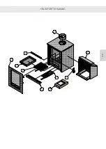
Page 147: ...1 2 3 4 5 9 6 7 8 10 GB SPARE PARTS DRAWING...
Page 149: ...2 9 6 7 8 10 1 3 4 5 GB SPARE PARTS DRAWING...
Page 151: ...2 9 6 7 8 10 1 3 4 5 GB SPARE PARTS DRAWING...
Page 153: ...10 1 7 8 2 3 4 9 6 5 GB SPARE PARTS DRAWING...
Page 154: ...GB...
Page 157: ...GB DECLARATION OF PERFORMANCE...
Page 198: ...1 2 3 4 5 9 6 7 8 10 F DESSIN DE PI CE DE RECHANGE...
Page 200: ...2 9 6 7 8 10 1 3 4 5 F DESSIN DE PI CE DE RECHANGE...
Page 202: ...2 9 6 7 8 10 1 3 4 5 F DESSIN DE PI CE DE RECHANGE...
Page 204: ...10 1 7 8 2 3 4 9 6 5 F DESSIN DE PI CE DE RECHANGE...
Page 205: ...F...
Page 208: ...F D CLARATION DES PERFORMANCES...
Page 209: ...NO...
Page 230: ...800 NO AVSTANDER Avstand til brennbart uisolert r ykr r Brennbart tak...
Page 232: ...800 NO AVSTANDER Avstand til brennbart uisolert r ykr r Brennbart tak...
Page 250: ...1 2 3 4 5 9 6 7 8 10 NO RESERVEDELSTEGNING...
Page 252: ...2 9 6 7 8 10 1 3 4 5 NO RESERVEDELSTEGNING...
Page 254: ...2 9 6 7 8 10 1 3 4 5 NO RESERVEDELSTEGNING...
Page 256: ...10 1 7 8 2 3 4 9 6 5 NO RESERVEDELSTEGNING...
Page 257: ...NO...
Page 260: ...NO YTELSESERKL RING...
Page 261: ...S...
Page 302: ...1 2 3 4 5 9 6 7 8 10 S RESERVDELSRITNING...
Page 304: ...2 9 6 7 8 10 1 3 4 5 S RESERVDELSRITNING...
Page 306: ...2 9 6 7 8 10 1 3 4 5 S RESERVDELSRITNING...
Page 308: ...10 1 7 8 2 3 4 9 6 5 S RESERVDELSRITNING...
Page 309: ...S...
Page 312: ...S PRESTANDADEKLARATION...
Page 313: ......
Page 354: ...1 2 3 4 5 9 6 7 8 10 SF VARAOSAPIIRUSTUS...
Page 356: ...2 9 6 7 8 10 1 3 4 5 SF VARAOSAPIIRUSTUS...
Page 358: ...2 9 6 7 8 10 1 3 4 5 SF VARAOSAPIIRUSTUS...
Page 360: ...10 1 7 8 2 3 4 9 6 5 SF VARAOSAPIIRUSTUS...
Page 361: ...SF...
Page 364: ...SF SUORITUSTASOILMOITUS...

