1
2
3
4
1
2
3
4
1
2
3
4
GB
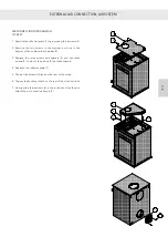
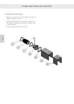
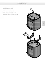
EXTERNAL AIR CONNECTION, AIRSYSTEM
EXTERNAL AIR CONNECTION, AIRSYSTEM
All RAIS/ATTIKA wood-burning stoves can be supplied with
external air. We call this external air supply AirSystem. The air
intake to the system can be concealed by installing it in either
the floor or the wall behind the stove.
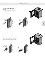
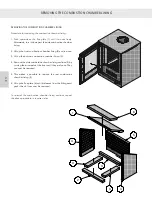
AIR CONNECTION THROUGH THE FLOOR
Q-TEE 57
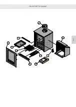
1. Remove the reflector plate (1) by removing the 4 screws (2).
2. Tap out the knockout blank in the reflector plate using a
hammer.
3. Remove the two screws in the damper and one in the
bottom of the combustion chamber (3).
4. Replace the three screws with spacers (4) and use these
screws (3) to mount the air box on these spacers.
5. Reattach the reflector plate (1).
Summary of Contents for Attika Q-Tee C 57 Classic
Page 2: ...DK DK DK DK...
Page 43: ...1 2 3 4 5 9 6 7 8 10 DK 42 RESERVEDELSTEGNING DK DK DK DK...
Page 45: ...2 9 6 7 8 10 1 3 4 5 DK 44 RESERVEDELSTEGNING DK DK DK DK...
Page 47: ...2 9 6 7 8 10 1 3 4 5 DK 46 RESERVEDELSTEGNING DK DK DK DK...
Page 49: ...10 1 7 8 2 3 4 9 6 5 DK 48 RESERVEDELSTEGNING DK DK DK DK...
Page 50: ...49 DK DK DK DK DK...
Page 53: ...DK 52 YDEEVNEDEKLARATION DK DK DK DK...
Page 54: ...D...
Page 95: ...1 2 3 4 5 9 6 7 8 10 D ERSATZTEILZEICHNUNG...
Page 97: ...2 9 6 7 8 10 1 3 4 5 D ERSATZTEILZEICHNUNG...
Page 99: ...2 9 6 7 8 10 1 3 4 5 D ERSATZTEILZEICHNUNG...
Page 101: ...10 1 7 8 2 3 4 9 6 5 D ERSATZTEILZEICHNUNG...
Page 102: ...D...
Page 103: ...D PR FUNGSBESCHEINIGUNG...
Page 105: ...D LEISTUNGSERKL RUNG...
Page 106: ...GB...
Page 147: ...1 2 3 4 5 9 6 7 8 10 GB SPARE PARTS DRAWING...
Page 149: ...2 9 6 7 8 10 1 3 4 5 GB SPARE PARTS DRAWING...
Page 151: ...2 9 6 7 8 10 1 3 4 5 GB SPARE PARTS DRAWING...
Page 153: ...10 1 7 8 2 3 4 9 6 5 GB SPARE PARTS DRAWING...
Page 154: ...GB...
Page 157: ...GB DECLARATION OF PERFORMANCE...
Page 198: ...1 2 3 4 5 9 6 7 8 10 F DESSIN DE PI CE DE RECHANGE...
Page 200: ...2 9 6 7 8 10 1 3 4 5 F DESSIN DE PI CE DE RECHANGE...
Page 202: ...2 9 6 7 8 10 1 3 4 5 F DESSIN DE PI CE DE RECHANGE...
Page 204: ...10 1 7 8 2 3 4 9 6 5 F DESSIN DE PI CE DE RECHANGE...
Page 205: ...F...
Page 208: ...F D CLARATION DES PERFORMANCES...
Page 209: ...NO...
Page 230: ...800 NO AVSTANDER Avstand til brennbart uisolert r ykr r Brennbart tak...
Page 232: ...800 NO AVSTANDER Avstand til brennbart uisolert r ykr r Brennbart tak...
Page 250: ...1 2 3 4 5 9 6 7 8 10 NO RESERVEDELSTEGNING...
Page 252: ...2 9 6 7 8 10 1 3 4 5 NO RESERVEDELSTEGNING...
Page 254: ...2 9 6 7 8 10 1 3 4 5 NO RESERVEDELSTEGNING...
Page 256: ...10 1 7 8 2 3 4 9 6 5 NO RESERVEDELSTEGNING...
Page 257: ...NO...
Page 260: ...NO YTELSESERKL RING...
Page 261: ...S...
Page 302: ...1 2 3 4 5 9 6 7 8 10 S RESERVDELSRITNING...
Page 304: ...2 9 6 7 8 10 1 3 4 5 S RESERVDELSRITNING...
Page 306: ...2 9 6 7 8 10 1 3 4 5 S RESERVDELSRITNING...
Page 308: ...10 1 7 8 2 3 4 9 6 5 S RESERVDELSRITNING...
Page 309: ...S...
Page 312: ...S PRESTANDADEKLARATION...
Page 313: ......
Page 354: ...1 2 3 4 5 9 6 7 8 10 SF VARAOSAPIIRUSTUS...
Page 356: ...2 9 6 7 8 10 1 3 4 5 SF VARAOSAPIIRUSTUS...
Page 358: ...2 9 6 7 8 10 1 3 4 5 SF VARAOSAPIIRUSTUS...
Page 360: ...10 1 7 8 2 3 4 9 6 5 SF VARAOSAPIIRUSTUS...
Page 361: ...SF...
Page 364: ...SF SUORITUSTASOILMOITUS...


